Alignment
Description
This Step adjusts the translation, rotation, and scaling of the input image to align it with the model image in the 2D plane, ensuring the consistency between the two.
Workflow
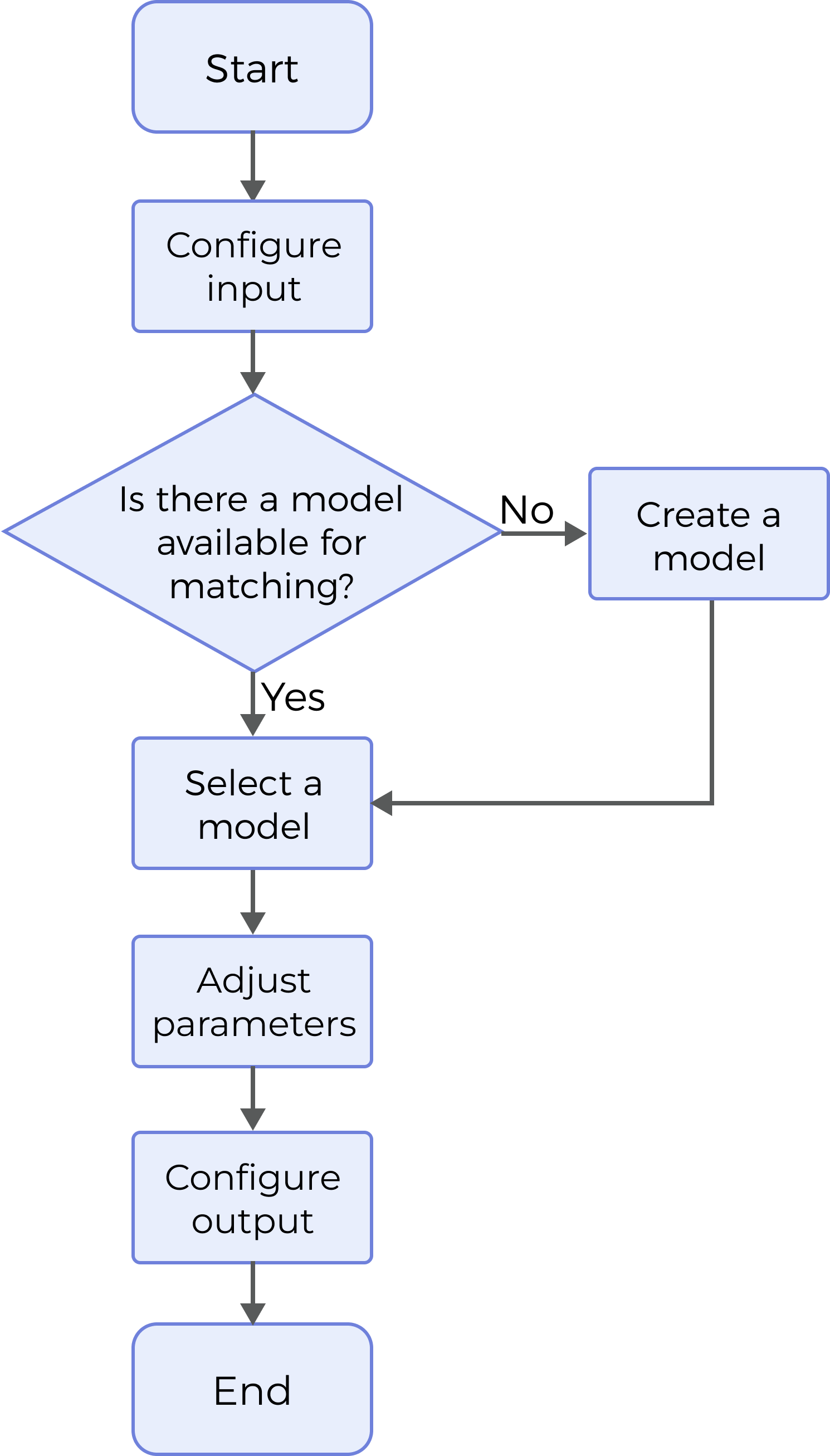
The process of configuring this Step is shown below.

-
Configure the input. Connect the ports manually or select the input(s) under Input in the parameter configuration panel.
-
Make and select a model. For more information on how to make a model, please refer to 2D Model Editor.
-
Set Matching Parameters.
-
Select the desired output(s) under Output. For an expandable output item, click ▶ and configure the Min and Max values of the acceptable range.
Parameter Description
| Parameter | Description | ||
|---|---|---|---|
Use Intensity Image |
This parameter determines whether to use intensity image. Once this parameter is selected, the input intensity image will be used for matching with an intensity image model. It is not checked by default. |
||
Use Feature Region |
Feature region defines the area to be processed by the algorithm. When this option is selected, this Step will only process data within the feature region.
|
Model Settings
| Parameter | Description | ||
|---|---|---|---|
Select Model |
This parameter is used to set the matching model. Click Edit Model to open 2D Model Editor, where you can edit the model for alignment. After setting and saving the model, click ▼ and select the model in the drop-down menu. For instructions on how to use the editor, please refer to 2D Model Editor.
|
Matching Settings
| Parameter | Description | ||
|---|---|---|---|
Pyramid Level |
This parameter determines from which level of the pyramid to start for downward model matching.
|
||
Matching Score Threshold |
This parameter is used to determine whether a matching result is valid. Result with a matching score below this threshold will be discarded. Default setting: 50.0 |
||
Max Padding Size |
This parameter determines the maximum number of pixels to be padded. Default setting: 0
|
||
Max Overlap Ratio |
This parameter defines the upper limit of the overlap ratio if there is an overlap between two matching results. If the overlap ratio is above the set value, the result with the higher matching score will be retained, while the result with the lower score will be discarded. Default setting: 0.40 |
||
Skip Lowest Level |
This parameter is used to determine whether to ignore the lowest level of the pyramid during matching. The parameter is selected by default, and it can accelerate matching. |
Refinement Setting
| Parameter | Description | ||
|---|---|---|---|
Use Non Rigid Refinement |
Once this option is selected, a non-rigid method for pose refinement will be used.
|
||
Search Radius |
This parameter is used to set the radius when searching for the corresponding point in pose refinement. Default setting: 10
|
||
Canny Low Threshold |
This parameter determines the minimum number of edge pixels to be extracted during pose refinement. A lower value implies a greater number of pixels recognized as edges. Default setting: 30 |
||
Canny High Threshold |
This parameter determines the maximum number of edge pixels to be extracted during pose refinement. A higher value implies a smaller number of pixels recognized as edge points. Default setting: 60 |
||
ICP Model Downsampling Step |
This parameter specifies the step size for model downsampling, accelerating the matching. Increasing this value will help speed up pose refinement but may decrease the accuracy. Default setting: 1 |
||
ICP Scene Downsampling Step |
This parameter specifies the step size for scene downsampling, accelerating the matching. Increasing this value will help speed up pose refinement but may decrease the accuracy. Default setting: 1 |
Output Description
Select the output item(s) to add the output port(s) to the Step, and the corresponding data will be output after the Step is run. You can select the output according to the actual measurement requirements.
|
If you select an expandable output item, you must expand it by clicking ▶, and then set the Min and Max values to determine the acceptable range. If the output value falls within the acceptable range, the measurement item is judged as passing (OK), or else it is judged as failing (NG). |
| Output Item | Description | ||
|---|---|---|---|
Surface Data |
The surface data after alignment. |
||
Confidence |
The confidence of the matching result or the accuracy of the match. |
||
Alignment Parameter Group |
A parameter group containing the coordinates of the reference point and the reference orientation.
|
Troubleshooting
See Error Code List for common error messages and solutions.