Measure Cylinder
Description
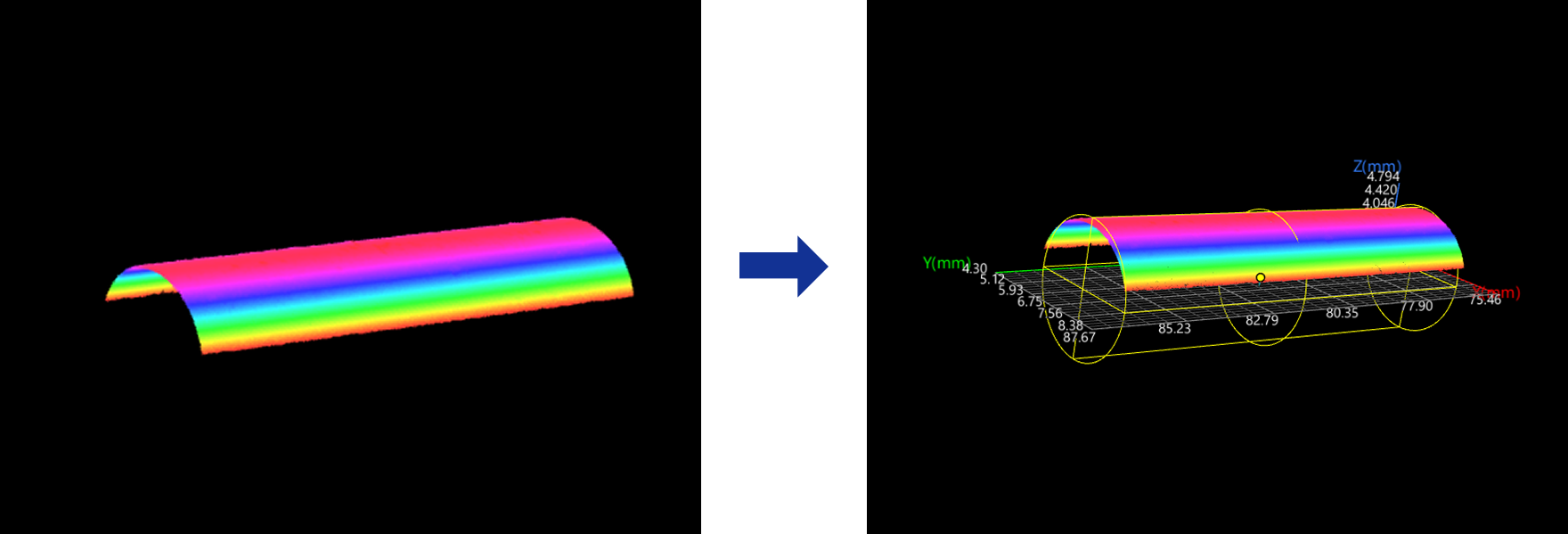
Use this Step to fit the cylinder from the surface data and calculate cylinder’s radius, center point, tilt angle, etc.
Workflow
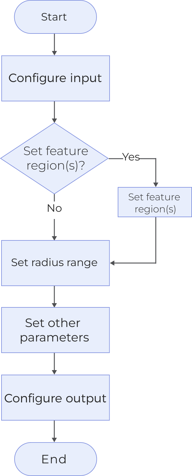
The process of configuring this Step is shown below:
-
Configure the input. Connect the Step ports in the graphical programming workspace or select the input under Input in the parameter configuration panel.
-
Determine whether to use a feature region.
-
Set the radius range of the cylinder.
-
Set other parameters.
-
Select the desired output items under Output. For an expandable output item, click ▶ and configure the Min and Max values to determine the acceptable range for the item.
Parameters
| Parameter | Description | ||
|---|---|---|---|
Use Feature Region |
When unselected, the Step processes all of the surface data to fit the cylinder. Otherwise, the Step will process surface data inside the region when the feature region is used. At this point, the following parameters need to be set:
|
||
Max Radius |
The radius of the fitted cylinder must not exceed this value. |
||
Min Radius |
The radius of the fitted cylinder must be equal to or greater than this value. |
||
Distance Tolerance |
A point is considered an inlier if its distance to the surface of the fitted cylinder is within the tolerance. |
||
Percentage of Inliers for Fitting |
Specifies the proportion of inliers used for optimal cylinder fitting. |
||
Fitting Accuracy |
Determines how accurate the fitted cylinder is. Typically, higher accuracy requires more iterations and increases computational cost.
|
||
Max Iterations |
The maximum number of attempts the algorithm will make to fit an optimal cylinder. Iteration stops once this limit is reached. |
Output Description
Select the output item(s) to add the output port(s) to the Step, and the corresponding data will be output after the Step is run. You can select the output according to the actual measurement requirements.
|
If you select an expandable output item, you should expand it by clicking ▶, and then set the Min and Max values to determine the acceptable range. If the output value falls within the acceptable range, the measurement item is judged as passing (OK), or else it is judged as failing (NG). |
| Output item | Description |
|---|---|
Radius |
The radius of the fitted cylinder. |
Cylinder Center X/Y/Z |
The center point of the fitted cylinder. |
Axis–Z Angle |
The angle between the axis of the fitted cylinder and the Z–axis. |
Axis–X Angle |
The angle between the axis of fitted cylinder and X–axis. |
X/Y/Z-Component of Axis Vector |
The X, Y, Z-components of the axis vector of the fitted cylinder, respectively. |
Troubleshooting
|
CV-W3801
Error: Unable to fit a cylinder within the specified radius range.
Possible causes:
-
The set radius range is invalid.
-
No cylinder surface exists within set radius range in fitting region.
Solutions:
-
Make sure the set radius range is valid.
-
Make sure the cylinder surface within set radius range exists in fitted region.
CV-W3802
Error: The “Min/Max Radius” value must exceed 0, and the “Min Radius” must not exceed the “Max Radius”. Please check and try again.
Solution: Make sure those values exceed 0, and the “Min Radius” must not exceed the “Max Radius”.
CV-W3803
Error: The “Distance Tolerance” value must be greater than or equal to 0. Please enter a valid value.
Solution: Make sure the parameter value is greater than or equal to 0.
CV-W3804
Error: The “Percentage of Inliers for Fitting” value must be a percentage between 0% and 100%. Please enter a valid value.
Solution: Make sure the parameter value is within 0–100%.