Use “2D Model Editor” to Generate and Edit Models
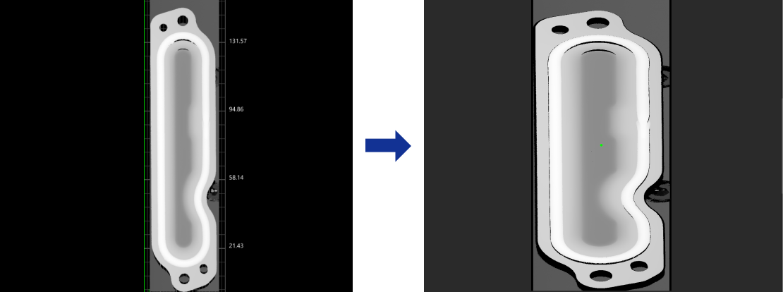
In 2D Model Editor, you can use tools to select 2D regions of interest (ROIs) on the depth map or intensity image. The points in the ROIs will be used as the feature points to generate a 2D model for matching. The Alignment Step will align the input image to the model, thus correcting the image so that the position of the target object remains consistent across all images.
The selected feature points should satisfy the following requirements:
-
Common to all images: If the selected feature points are not common to all images, matching between input images and the model may fail.
-
Representative: The selected feature points should be representative to ensure that the matching results are unique and accurate; otherwise, the matching results may be incorrect.
-
Moderate quantity: Generally, the more feature points selected, the higher the matching accuracy. However, if there are too many feature points, the matching speed may be reduced.
Preparations
-
Make sure that the Alignment Step has valid input.
-
Under Parameters in the parameter configuration panel of the Alignment Step, click the Edit Model button to open the 2D Model Editor. This tool will automatically obtain the input image of the Step.

|
Workflow
-
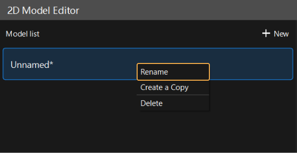
Rename the default model or click the + New button to create a new model.
After selecting a model from in the model list, right-click and select the Rename option, enter a custom name, and click the OK button to modify the model name. 
-
Select feature points. The selected feature points should be representative, and the quantity should be appropriate.
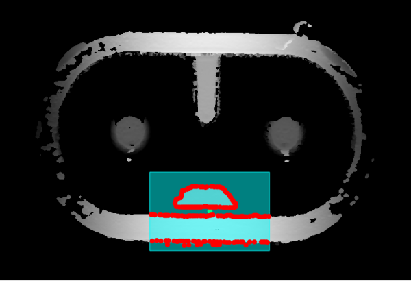
Instruction: Click the icon on the toolbar to the right of the Model list to select the appropriate ROI Drawing Tools and create ROIs to cover feature points in the image. Note that when a feature region is used in the Alignment Step, the selected feature points are valid only when they are also within the feature region. If not, the generated matching model may lead to matching failure.
-
In the ROI list section at the bottom left of the interface, right-click an ROI and select Enable, Disable, etc., to set the drawn ROI.
-
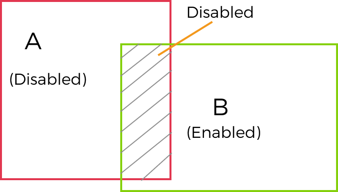
For overlapping areas, Disable has priority over Enable. In other words, when two regions are set to Enable and Disable separately, the actual status of the overlapped region is Disable, and the feature points in the overlapped region do not take effect and will not be used for model generation.

-
-
Set the center point. The model rotates around the center point within a specified angle range to accommodate different angle variations of the target in the image.
If the center point is changed after the model is generated, you must click the Generate Model button again to update the model for the center point setting to take effect. -
Set Feature parameters.
-
Click the Generate model button in the lower-right corner to generate and preview the model.

-
Click the Save button in the lower-right corner to save the generated model.
If you only clicked Save in the lower-right corner and did not generate a model, the edited model would be saved but would not work.
After configuration, close the editor. Click ▼ under the Edit Model button in the Parameters section of the Alignment Step and then select the corresponding model in the drop-down menu.
ROI Drawing Tools
The usage instructions on ROI drawing tools are shown in the table below.
| Icon | Tool | Instructions |
|---|---|---|
|
Circle ROI Tool |
Use the Circle ROI Tool to draw a circular ROI.
|
|
Rectangle ROI Tool |
Use the Rectangle ROI Tool to draw a rectangular ROI.
|
|
Polygon ROI Tool |
Use the Polygon ROI Tool to draw a polygonal ROI.
|
|
ROI Eraser Tool |
Use the ROI Eraser Tool to erase the drawn ROI, and the points in the erased parts will not be used to generate the model.
|
|
Select Tool |
Use the Select Tool to select and edit the drawn ROI.
|
|
Feature Parameters
| Parameter | Description | ||
|---|---|---|---|
Gradient magnitude threshold |
Points with gradient magnitude greater than the threshold will be considered feature points. Set this parameter to filter out feature points with small gradient magnitude. When a high threshold is set, only points with large gradient magnitude, i.e., points that vary significantly in the image, will be kept. When a low threshold is set, some noise or insignificant feature points may be kept. |
||
Number of feature points |
The expected number of feature points extracted from the model image. A greater value means a larger feature point count.
|
||
Kernel Size of NMS |
The kernel size of non-maximum suppression (NMS). This parameter is used to regulate the distribution density of the feature points. The larger the value, the sparser the feature points. |
||
Set Angle |
Set the angle-related parameters to define the allowable rotation angle range of the image to be aligned.
|
||
Set scale |
Set the scale-related parameters to define the allowable scale range of the image to be aligned.
|