Configure Display Windows
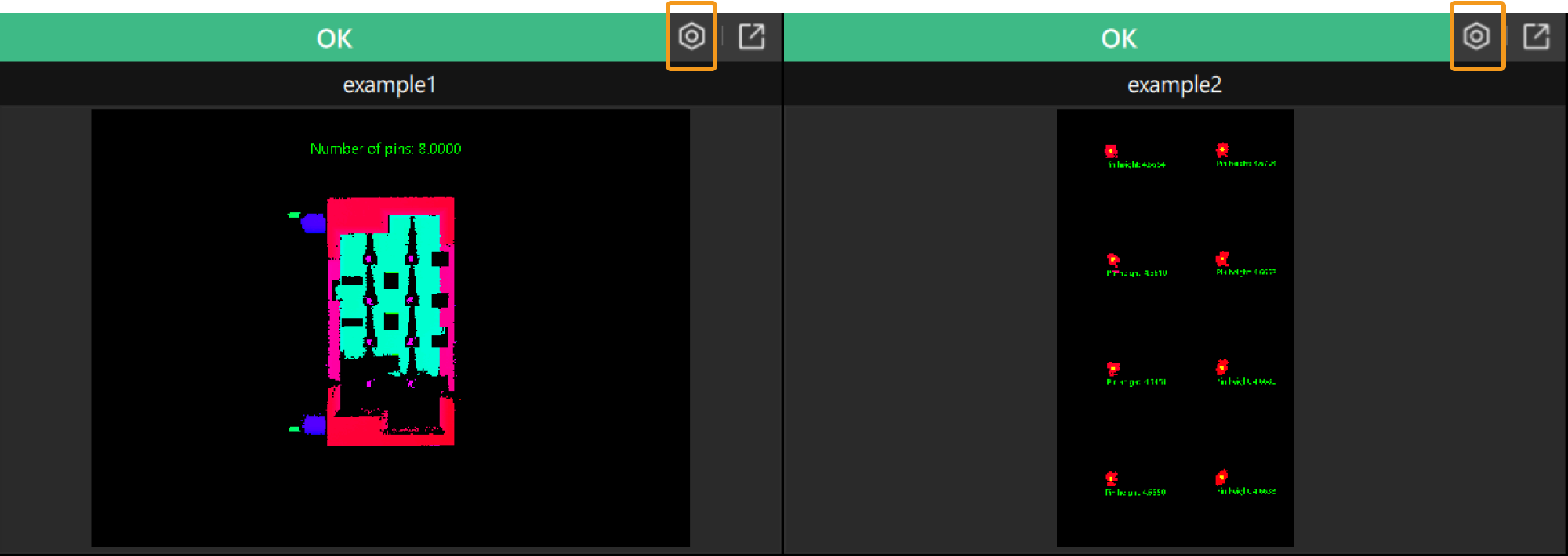
According to the configured Image layout, the production interface mainly displays several image windows, allowing users to intuitively view the image data.
Click the configuration icon ![]() at the upper-right corner of each display window and configure the image to be displayed in the pop-up window.
at the upper-right corner of each display window and configure the image to be displayed in the pop-up window.
Configuration Process
Follow the steps below to configure each display window:
-
(Optional) Set graphics overlays.
-
(Optional) Set text overlays.
Once the settings are completed, click the Save button to save the changes, and the configured image will be displayed in the display window.
|
To zoom in on the image, click the icon |
Image Settings
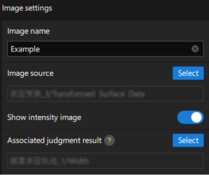
According to the actual requirements, set the image content displayed in the window.
| Parameter | Description | Illustration |
|---|---|---|
Image name |
The set image name will be displayed at the top of the window. |
|
Image source |
Click the Select button to select the image to be displayed in the window. |
|
Show intensity image |
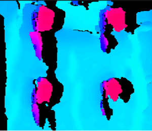
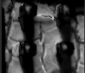
By default, the depth map is displayed in the window. Once this feature is enabled, the intensity image will be displayed. |
|
Associated judgment result |
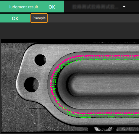
Click the Select button to select a measurement item to associate. The judgment result for the associated measurement item is the judgment result of the image. The judgment result will be displayed in the upper-left corner of the window, with green indicating OK and red indicating NG. |
- |
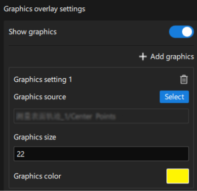
Graphics overlay settings
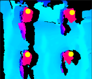
Enable the Show graphics feature to set the graphics overlays.
| Parameter | Description | Illustration |
|---|---|---|
Graphics source |
Click the Select button to select the source of graphics overlays. |
|
Graphics size |
The size of the graphics overlays. |
|
Graphics color |
Click the bright yellow (default) color block on the right side of this option to customize the graphics color. |
|
Text overlay settings
Enable the Show text feature to set the text overlays.
| Parameter | Description | Illustration | ||
|---|---|---|---|---|
Text content |
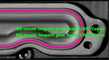
The text overlaying the image consists of two parts: custom text + inserted measured value. After entering the custom text, click the Insert measured value button and select the measured value to insert to finish the setting of the text content.
|
|
||
Text position |
You can determine the position of the text overlays by setting related parameters.
If the text position does not meet your expectations, you can adjust the following parameters:
|
|
||
Text style |
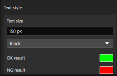
According to the actual requirements, customize the Text size and color. |
|
