Measure Surface Track
Description
Use pre-defined track lines and measurement parameters to inspect whether the height, width and position of a track in the surface data are qualified, thereby detecting overflow, breakage, and other issues.
Basic Concepts
Track and track line
-
Track
The target of measurement, usually refers to glue bead lines. The “Measure Surface Track” Step can be used to measure the width, height, and position of tracks and judge whether the dimensions of all kinds can meet the requirements.
-
Track line
The line that a track should follow, ideally the centerline of a track. Track lines should be manually drawn. See Track Line Editor for details on how to create and adjust track lines.
|
As shown in the figure, the track is light gray, and the track line is the cyan line. |
Section profile, peak point, side point, and center point
Sampling section profiles from the surface data of the track can help judge whether the dimensions of the track, such as height and width, can meet the standards.
-
Section profile
Every time a section is sampled from the surface data of the track, a section profile of the track can be obtained. On this basis, the measurement of dimensions, such as height and width, can be performed.
-
Peak point
The point with the greatest height on each profile. See Peak Point Detection for details.
-
Side point
There are two side points for each profile, which reflect the farthest points on both sides of the track. The distance between the points after projection onto the XOY plane is the track width at a section. See Side Point Detection for details.
-
Center points
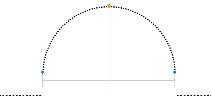
The center point is on the section profile, with its X and Y coordinates matching the midpoint of the two side points on the XOY plane. The center point does not necessarily coincide with the peak point.
The offset refers to the difference between the center point and the track line on the XOY plane. If the offset value is outside of the acceptable range, the corresponding center point is judged as unqualified (NG). Such a case shows that the track at the section may have issues such as overflow and breakage. These issues need to be clarified according to the actual situation. The center point is displayed in green when judged as OK, and in red when judged as NG.

As shown in the figure, a peak point (in orange), two side points (in dark blue), and an OK center point (in green) can be detected from the section profile.
Workflow
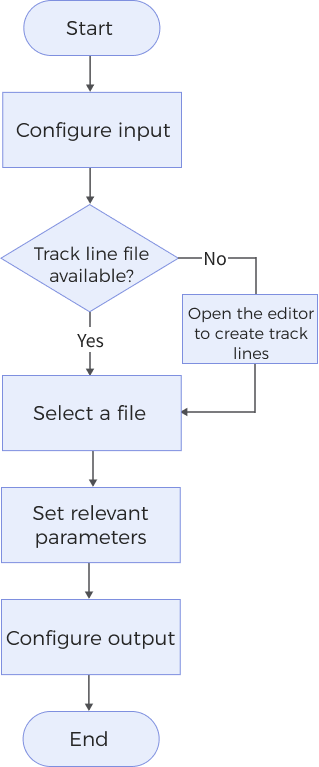
The process of configuring this Step is shown below.

-
Configure the input. Connect the Step ports in the graphical programming workspace or select the input under Input in the parameter configuration panel.
-
Select or create a track line file. See Track Line Editor to learn how to create or adjust track lines.
-
Set the parameters under Detection Settings, Judgment Settings, and Display Settings.
-
Select the desired output items under Output. For an expandable output item, click ▶ and configure the Min and Max values to determine the acceptable range for the item.
Parameter Description
Track Line Settings
| Parameter | Description |
|---|---|
Select Track Line File |
Select a track line file from the drop-down list. The track line file is used to determine the path that the track should follow and contains settings related to sampling section profiles from the track. |
| See the instructions on Track Line Editor to learn how to create and adjust track lines. |
Detection Settings
| Parameter | Description | ||
|---|---|---|---|
Interpolation Along Profiles |
Select this parameter to enable linear interpolation on section profiles and thus make the track width and height measurements more accurate. |
||
Use Height Filter |
After selecting this option, set a height range for data points on the section profiles to filter out noise or useless data points. Once this parameter is selected, set Max Height and Min Height to determine the height range for data points to be retained. |
||
Use Median Filter |
Select this parameter to perform median filtering on the section profiles and thus make them smoother. You need to set the Window Size for median filtering. |
||
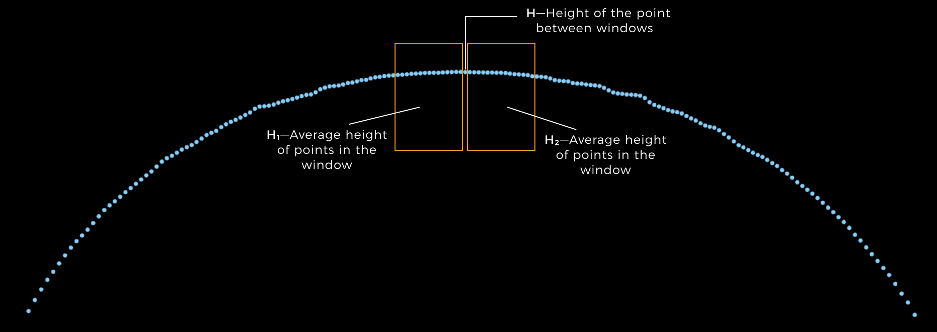
Window Size for Peak Detection |
The size of windows for detecting the peak points of a section profile. The two windows are separated by a point on the profile.
|
||
Peak Detection Threshold |
A point is considered a candidate peak point when its height exceeds the average heights of points in both the left and right windows by the set “Peak Detection Threshold.” The candidate peak point with the largest average height difference over both windows is then considered a peak point. |
||
Height Mode |
This parameter is used to determine the meaning of Nominal Height.
|
||
Side Detection Method |
The method for detecting track sides from section profiles to better determine the side points. When the slope of track sides is steep, select Maximum gradient; otherwise, select Height threshold. |
||
Side Window Size |
The window size for detecting the side points from both sides of section profiles.
This parameter is only visible when the “Side Detection Method” is set to Maximum gradient. |
||
Max Track Width |
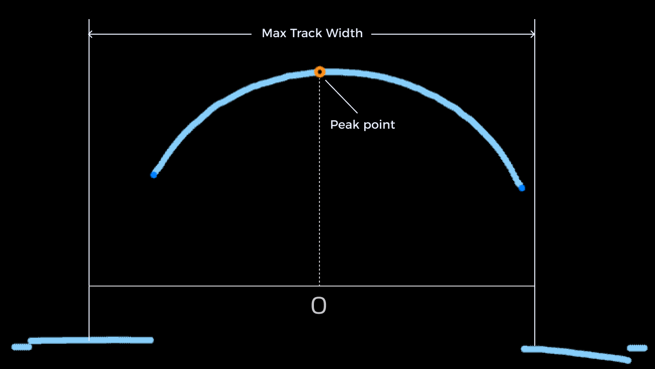
The width range of the section profile considered during side point detection, centered on the peak point. This parameter is only visible when the “Side Detection Method” is set to Maximum gradient.

|
||
Side Height Threshold |
During side point detection from a section profile, side points are the leftmost and rightmost points with height values below the set threshold. This parameter is only visible when the “Side Detection Method” is set to Height threshold. |
||
Gap Filling Threshold |
The data points on a section profile may have gaps due to occlusion. When the size of a gap on a profile is less than or equal to the set threshold, use the nearest valid point from the lower side of the gap to fill the gap. When the gap size exceeds the set threshold, leave the gap as null point(s). 
|
||
Include Null Points |
Use this parameter to determine whether to include null points or not in the detection process. (Null points are points without depth or intensity information, which are often the result of data loss.) Once this parameter is selected, set Null Filling Value of Depth.
|
||
Null Filling Value of Depth |
A depth value for filling null points. Only needs to be set after Include Null Points is selected. |
Judgment Settings
| Parameter | Description |
|---|---|
Nominal Width |
The expected width of the track. |
Width Tolerance |
The maximum acceptable deviation of the actual track width from the nominal width. |
Nominal Height |
The expected height of the track. |
Height Tolerance |
The maximum acceptable deviation of the actual track height from the nominal height. |
Nominal Cross-Sectional Area |
The expected cross-sectional area of the track. |
Cross-Sectional Area Tolerance |
The maximum acceptable deviation of the actual cross-sectional area from the nominal cross-sectional area. |
Offset Tolerance |
The maximum allowed distance between center points and track line. |
Display settings
| Parameter | Description |
|---|---|
Show Track Line and Profile Spacing |
Select this parameter to show the selected track line(s) and profile spacing in the data visualization window. |
Show Measured Results |
Select this parameter to show all section profiles and their respective center points and peak points obtained through measurement in the data visualization window. |
Output Description
Select the output item(s) to add the output port(s) to the Step, and the corresponding data will be output after the Step is run. You can select the output according to the actual measurement requirements.
|
If you select an expandable output item, you should expand it by clicking ▶, and then set the Min and Max values to determine the acceptable range. If the output value falls within the acceptable range, the measurement item is judged as passing (OK), or else it is judged as failing (NG). |
| Output item | Description |
|---|---|
OK Count |
The number of section profiles that satisfy the requirements of all judgment settings. |
NG Count |
The number of section profiles that cannot satisfy the requirements of all judgment settings. |
Min Width |
The measured minimum track width. |
Max Width |
The measured maximum track width. |
Mean Width |
The mean of all measured track widths. |
Min Height |
The measured minimum track height. |
Max Height |
The measured maximum track height. |
Mean Height |
The mean of all measured track heights. |
Min Cross-Sectional Area |
The measured minimum cross-sectional area of the track. |
Max Cross-Sectional Area |
The measured maximum cross-sectional area of the track. |
Mean Cross-Sectional Area |
The mean of all measured cross-sectional areas of the track. |
Cross-Sectional Area |
The cross-sectional areas measured from all section profiles. |
Width |
The track widths measured from all section profiles. |
Height |
The peak heights measured from all section profiles. |
Offset |
The measured offsets of all center points from the selected track line. |
Center Points |
The center points measured from all section profiles. |
Appendix
Peak Point Detection
The detection of peak points relies on the settings of the Window Size for Peak Detection and Peak Detection Threshold parameters.
According to the set Window Size for Peak Detection, two sliding windows move along a section profile, always with a data point between them. As the windows slide, the average heights of the data points in the left and right windows are calculated, denoted as H1 and H2, respectively. The height of a data point between the windows is denoted as H. A point is considered a candidate peak point if it satisfies the following conditions:
H – H1 ≥ T ① |
H – H2 ≥ T ② |
where T represents the set Peak Detection Threshold. Of all candidate peak points, the candidate with the maximum value of [(H – H1) + (H – H2)]/2 is identified as the peak point.

Side Point Detection
Upon the detection of a peak point, two side points are identified on either side of the peak point. Side points are the furthest left and right points along the track section and are used for track width measurement. You can use one of the following methods to detect side points from each section profile.
-
Height Threshold
This method is suitable for tracks with gentle side slopes. Before side points detection starting from the peak point, mean filtering is applied on section profiles. The first points on the left and right sides with heights below the Side Height Threshold are identified as side points.
-
Maximum gradient
This method is suitable for tracks with steep side slopes. According to the set Side Window Size, two sliding windows move along a section profile, always with a data point between them. The average heights of the data points in the left and right windows are calculated to determine the height difference for the point between the windows. Within the range of the Max Track Width, the points with the greatest height gradient detected from the left and right sides of the peak point are identified as the side points.
Troubleshooting
|
CV-W3501
Error: The “Length” value set for section profiles is outside of the valid range.
Possible causes:
-
The parameter value is less than or equal to 0, or it is greater than the length of the longest side of the image.
-
Some vertices in the track line overlap, creating incorrect segments with a length of 0, which disrupts the normal generation of section profiles.
Solutions:
-
Ensure the parameter value is greater than 0 and less than the length of the longest side of the image.
-
Open the track line editor and select an expand the target track line in the “List of track lines.” Then, locate the incorrect segments, delete overlapped vertices, and save the changes.
CV-W3502
The “Width” value set for section profiles is outside of the valid range.
Possible cause: The parameter value is less than or equal to 0, or it is greater than the length of the longest side of the image.
Solution: Ensure the parameter value is greater than 0 and less than the length of the longest side of the image.
CV-W3503
Error: The “Window Size for Peak Detection” value is outside of the valid range.
Possible causes:
-
The parameter value is less than 0.
-
The parameter value is greater than the length of the longest side of the image.
-
The parameter value is greater than half the length of section profiles.
Solutions:
-
Ensure the parameter value is greater than 0.
-
Ensure the parameter value is less than the length of the longest side of the image.
-
Ensure the parameter value is less than half the length of section profiles.
CV-W3504
Error: The “Max Track Width” value is outside of the valid range.
Possible cause:
-
The parameter value is less than or equal to 0.
-
The parameter value is greater than twice the length of the longest side of the image.
Solution:
-
Ensure the parameter value is greater than 0.
-
Ensure the parameter value is less than twice the length of the longest side of the image.
CV-W3505
Error: The “Side Window Size” value is outside of the valid range.
Possible cause:
-
The parameter value is less than 0.
-
The parameter value is greater than the length of the longest side of the image.
-
The parameter value is greater than or equal to half the length of section profiles.
Solution:
-
Ensure the parameter value is greater than 0.
-
Ensure the parameter value is less than the length of the longest side of the image.
-
Ensure the parameter value is less than half the length of section profiles.
CV-W3506
Error: The “Window Size” value is outside of the valid range.
Possible cause:
-
The parameter value is less than 0.
-
The parameter value is greater than the length of the longest side of the image.
-
The parameter value is greater than or equal to the length of section profiles.
Solution:
-
Ensure the parameter value is greater than 0.
-
Ensure the parameter value is less than the length of the longest side of the image.
-
Ensure the parameter value is less than the length of section profiles.
CV-W3507
The drawn track line is not within the image.
Solution: Redraw or modify the track lines in the “Track Line Editor” to ensure the track lines are within the image.
CV-W3508
Error: The “Null Filling Value of Depth” value is not within the valid range.
Possible cause: The parameter value is less than −10000 or greater than 10000.
Solution: Make sure the parameter value is within −10000–10000.
CV-W3509
Error: The “Gap Filling Threshold” value is not within the valid range.
Possible cause: The parameter value is less than 0 or greater than the length of the longest side of the image.
Solution: Ensure the parameter value is greater than or equal to 0 and less than the length of the longest side of the image.
CV-W3510
Error: The set “Side Detection Method” is invalid.
Solution: Select a valid side detection method from the drop-down list.
CV-W3511
Error: The set “Height Mode” is invalid.
Solution: Select a valid height mode from the drop-down list.
CV-W3512
Error: The “Side Height Threshold” is outside of the valid range.
Possible cause: The parameter value is less than −10000 or greater than 10000.
Solution: Make sure the parameter value is within −10000–10000.
CV-W3513
Error: The “Max Height” is outside of the valid range.
Possible cause: The parameter value is less than −10000 or greater than 10000.
Solution: Make sure the parameter value is within −10000–10000.
CV-W3514
Error: The “Min Height” is outside of the valid range.
Possible cause: The parameter value is less than −10000 or greater than 10000.
Solution: Make sure the parameter value is within −10000–10000.
