Preparations
Select the Layout of Laser Profilers
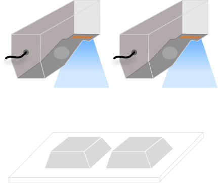
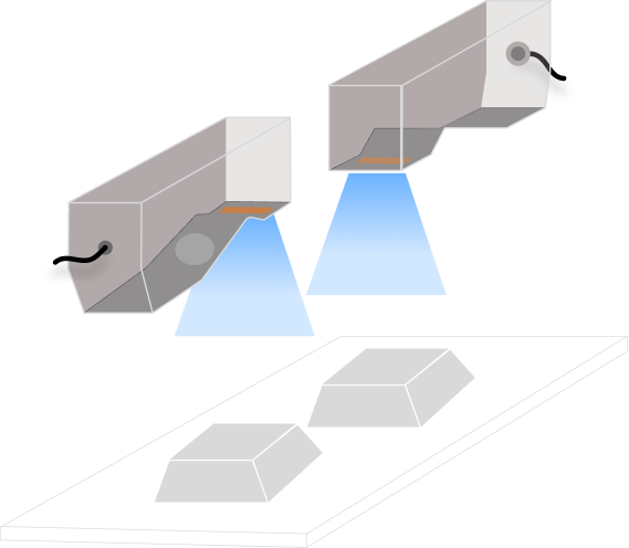
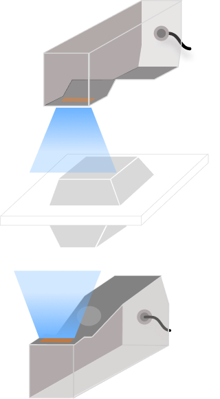
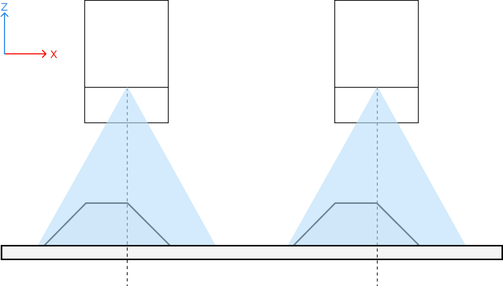
Laser profilers can be arranged in side-by-side, reverse, and opposite layouts.
| Side-by-side | Reverse | Opposite |
|---|---|---|
|
|
|
2 to 4 laser profilers |
2 laser profilers |
2 laser profilers |
| If the layouts mentioned above cannot meet the on-site demand, please contact Technical Support. |
Design and Machine the Calibration Target
Please follow the design and machining instructions to finish the design and machining of the calibration target.
|
Placement Requirements of Calibration Target
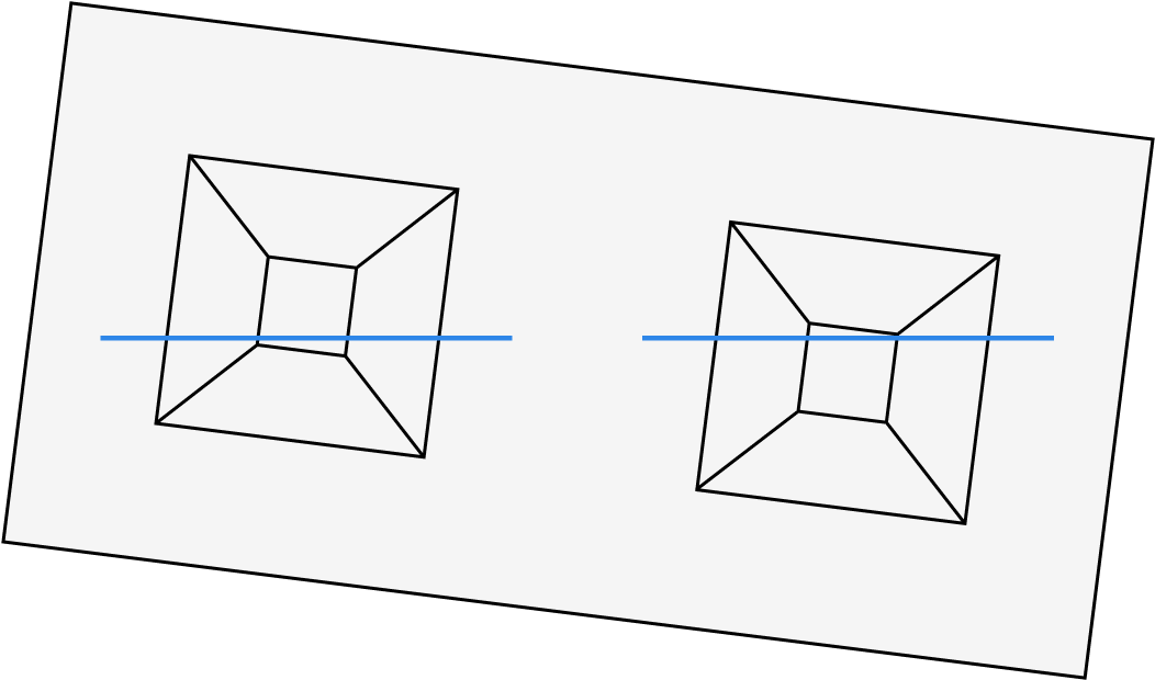
A calibration target consists of the frustum(s) and the foundation. Every laser profiler should capture a complete frustum and part of the foundation surface.
The following example, with two laser profilers in a side-by-side layout, illustrates the placement requirements for the calibration target:
-
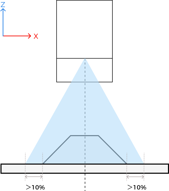
The frustum should be positioned at the center of the laser profiler’s FOV.
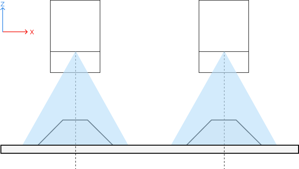


-
The four corners of the lower base of the frustum should be as far as possible from the edge of the FOV, with the distance being greater than 10% of the device’s X-axis measurement range.
-
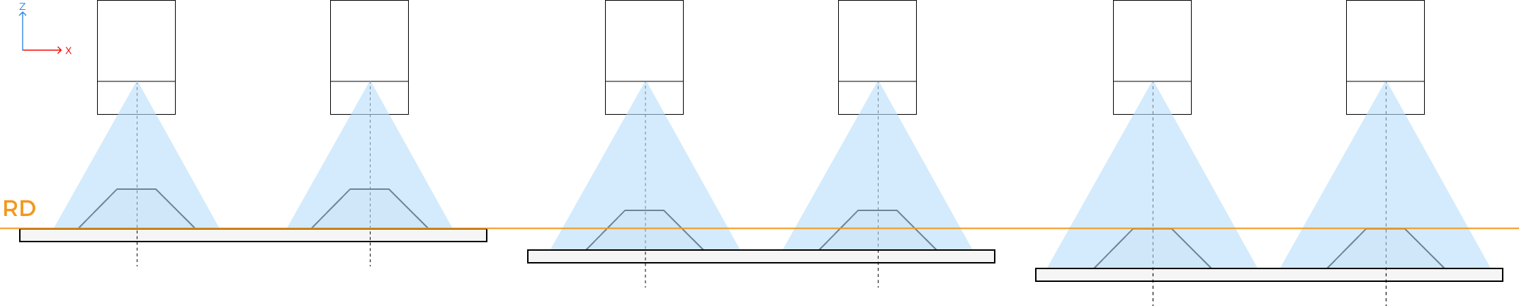
The distance from the lower base of the frustum to the laser emitter of the sensor head should be as close to the reference distance (RD) as possible.
-
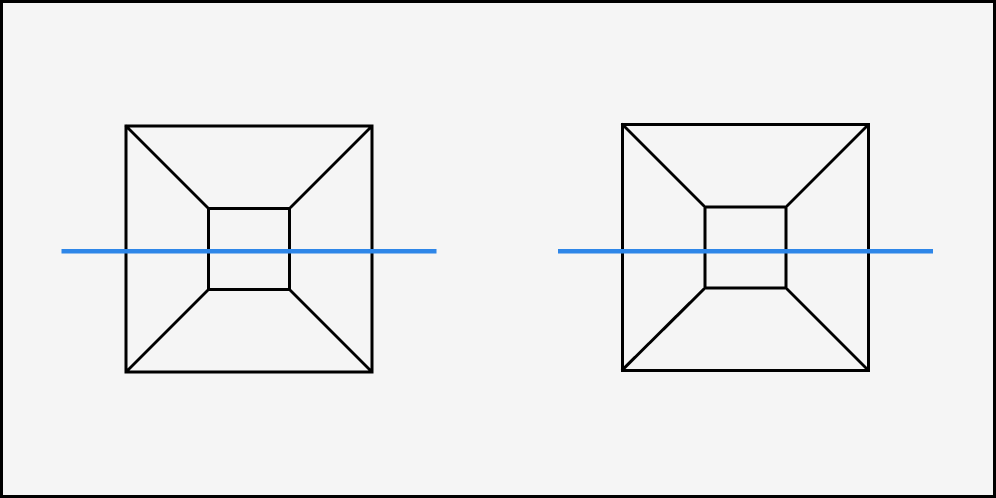
Four edges of the frustum should be parallel to the emitted laser lines.
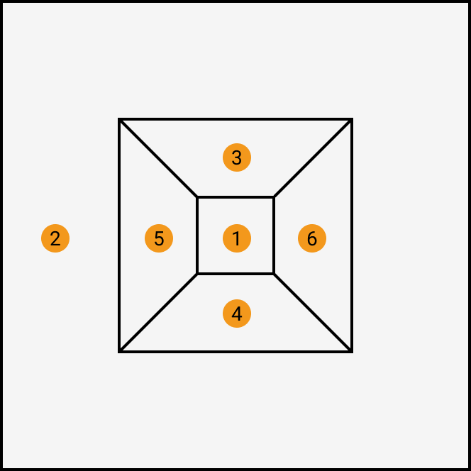
Scanning Range Requirements
Images acquired by every laser profiler should only include six feature surfaces of the calibration target, i.e., the upper base of the frustum (①), the foundation surface (②), and four side surfaces of the frustum (③④⑤⑥). Please make sure the scanning range of each laser profiler can completely cover the surfaces of the frustum and foundation, without any other surface data.
Acquire High-Quality Image Data
Refer to the Adjust Parameters section of Mech-Eye Viewer to make sure the acquired image data has no significant point loss and minimal noise.
After parameter adjustment, save the parameter group for the subsequent multiple laser profiler calibration.
Warm-Up Operation
Warm up the laser profilers before calibration to ensure calibration accuracy: After the devices are powered on, use them to acquire data continuously for more than one hour under the selected parameter groups.
Select a Calibration Scene
Before calibration, please select a calibration scene:
-
Calibrate a group of laser profilers with sensor heads arranged in a side-by-side, reverse, or opposite layout. After grouping and calibration, the acquired data can be stitched into a unified reference frame. The scene is suitable for simple data acquisition scenarios.
-
Combine multiple calibrated groups of laser profilers to meet the needs of complicated data acquisition scenarios, such as the combination of a side-by-side group and an opposite group and the combination of a side-by-side group and a reverse group. Ensure that each group shares at least one laser profiler with another group to form a connected whole.
Now, you can perform multiple laser profiler calibration in Mech-MSR.