Calibrate a Single Group
Navigate to the toolbar of Mech-MSR’s home interface, click the Multiple Laser Profiler Calibration button and then click the Preparations completed button in the pop-up window. Then, select the Calibrate a single group option and click the Start calibration button to enter the window of multiple laser profiler calibration.
 Connect to Laser Profilers
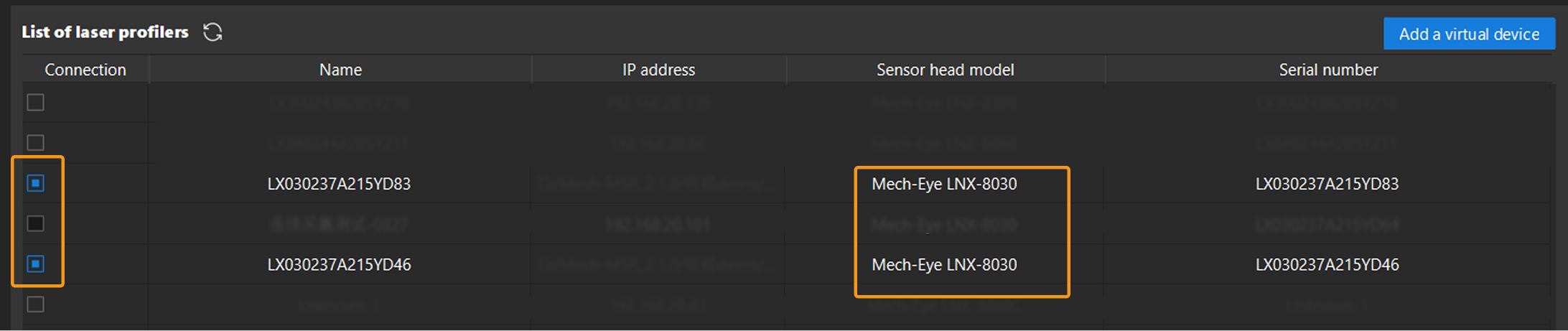
The laser profilers to be grouped should all use the same sensor head model. You can select laser profilers in the Connection column to connect to the devices.
|
After laser profilers are connected, click the Next button to proceed to layout settings.
 Select Layout
Layout options include side-by-side, reverse, and opposite. After selecting the layout according to the actual scenario, determine the arrangement sequence of the laser profilers’ sensor heads and the motion direction of the calibration target relative to them.
-
Number laser profilers
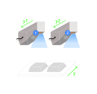
Laser profilers must be numbered correctly. After the primary laser profiler (numbered 1) is determined, data acquired by other laser profilers will be transformed into the reference frame of the data acquired by the primary laser profiler. Incorrect numbering will lead to inaccurate calibration results. Layout Description Illustration Side-by-side
The sensor heads of laser profilers are placed above the calibration target. Stand facing the sensor heads in the motion direction of the calibration target and number them from left to right in ascending order, with the leftmost sensor head as the primary (numbered 1).
Reverse
The sensor heads of laser profilers are placed above the calibration target. Stand facing the sensor heads in the motion direction of the calibration target and number them sensor from far to near in ascending order, with the farthest sensor head as the primary (numbered 1).

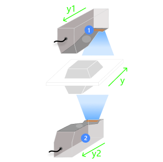
Opposite
Stand facing the sensor heads in the motion direction of the calibration target and number the sensor heads from top to bottom in ascending order, with the sensor head above as the primary (numbered 1).
-
Select correct parameter groups
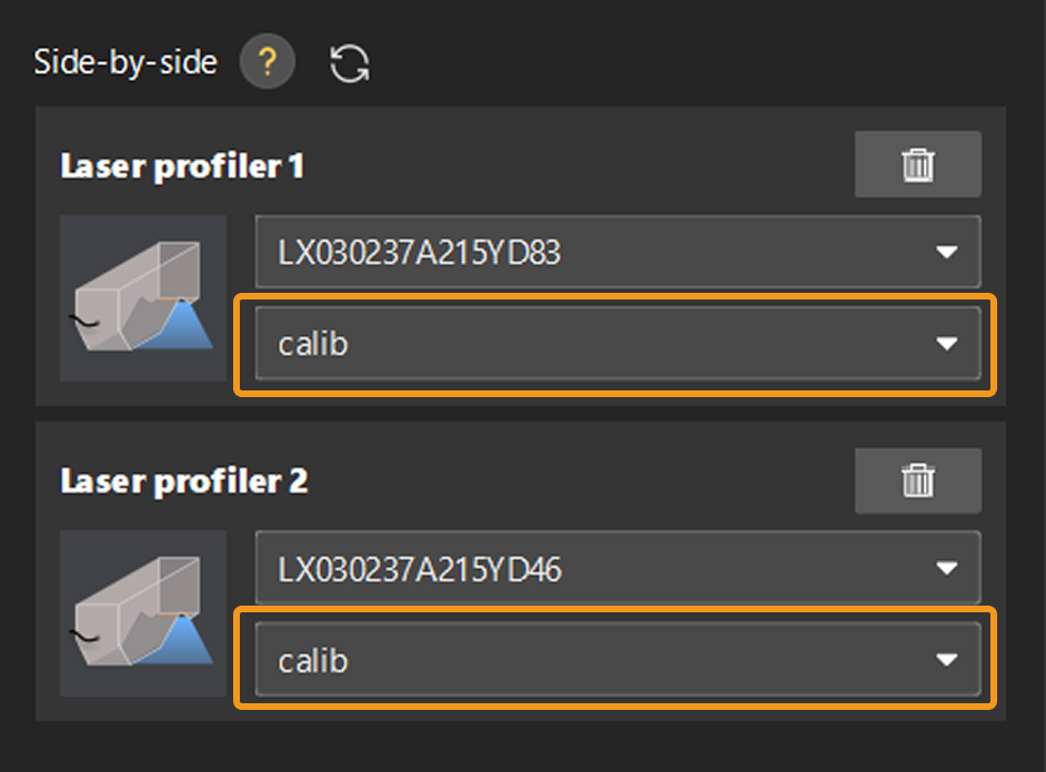
Select the parameter group saved in Mech-Eye Viewer for each laser profiler. By default, the parameter group is set to calib.
-
Laser profilers must have the same trigger and resolution settings, and the features of Profile Alignment, Correction, and Filters are not enabled for any of them. If the requirements cannot be fulfilled, please adjust the parameters in Mech-Eye Viewer and save the adjustment into the parameter group and then restart calibration in Mech-MSR.
-
If the FOVs of the laser profilers overlap, the laser profilers will interfere with each other if they emit laser light at the same time. In this case, you can set the Trigger Delay parameter for one of the laser profilers to solve this problem.
-
-
Determine the relative motion relationship between laser profilers and calibration target
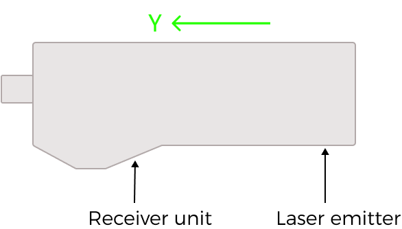
The Y-axis direction of a laser profiler is fixed, defined as the direction from the laser emitter of the sensor head to the sensor.
The motion direction of the calibration target matches that of the conveyor. If the calibration target remains stationary, its motion direction is defined as the motion direction relative to the sensor head.
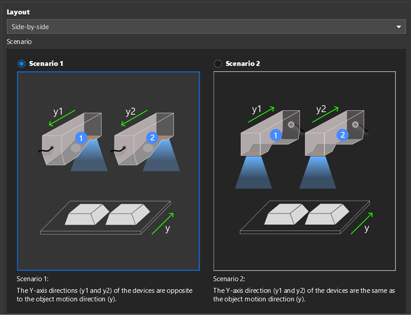
In actual scenarios, the direction of a laser profiler’s Y-axis can be the same as or opposite to the motion direction of the calibration target. When a laser profiler’s Y-axis direction is opposite to the calibration target’s motion direction, however, the acquired image will be mirrored. To resolve the issue of mirrored image, you can make appropriate settings based on the layout:
-
When the layout is Side-by-side or Opposite, select the right scenario.
-
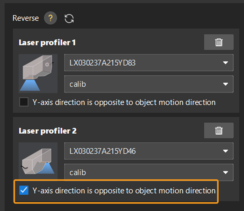
When the layout is Reverse, select the Y-axis direction is opposite to object motion direction option for one of the laser profilers.
The relationship between the laser profiler’s Y-axis direction and the calibration target’s motion direction must be set correctly. -
After the settings are completed, click the Next button to proceed to calibration target settings.
 Calibration Target Settings
Please enter parameter values according to the calibration target in use. The displayed parameters may vary under different layouts.
| Be sure to enter accurate parameter values. |

| Parameter | Description | ||
|---|---|---|---|
Upper base length (L1) |
The side length of the frustum’s smaller base. |
||
Lower base length (L2) |
The side length of the frustum’s larger base. |
||
Frustum height (h) |
The vertical distance from the upper base to the lower base of the frustum. |
||
Translation distance (d) |
The distance between the centerlines of neighboring frustums. When multiple frustums are arranged side by side on the calibration target, translating neighboring frustums by this distance will cause them to coincide.
|
||
Foundation thickness (h2) |
The thickness of the calibration target’ s foundation. |
||
Rotation radius (R) |
When there are multiple frustums on the calibration target, neighboring frustums will coincide after rotating around a specific point. The rotation radius refers to the distance from the center point of the frustum to this point. |
||
Rotation angle (α) |
When there are multiple frustums on the calibration target, neighboring frustums will coincide after rotating around a specific point. The rotation angle refers to the angle by which a frustum rotates around the point, allowing it to coincide with the neighboring frustum after rotation. |
After entering the accurate parameter values, click the Next button to proceed to calibration.
 Calibration
Follow the steps below to complete calibration:
-
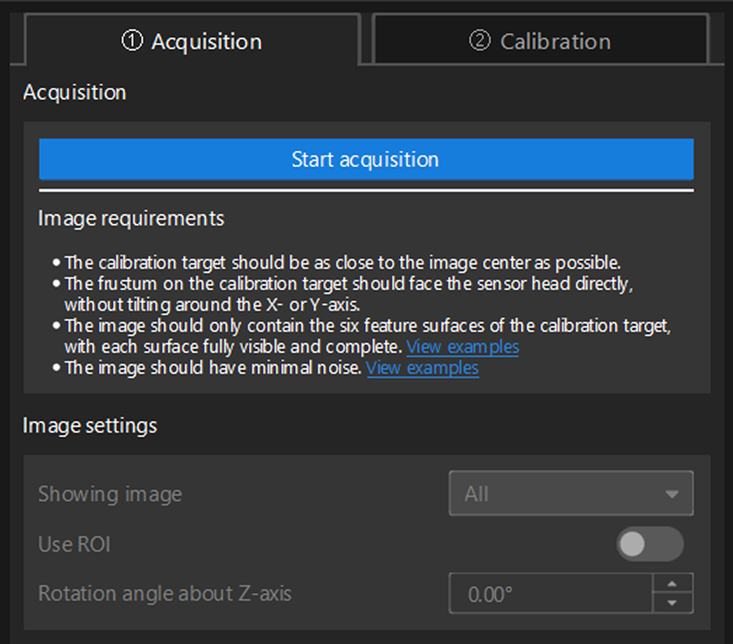
Under the Acquisition tab, click the Start acquisition button to acquire image data.
-
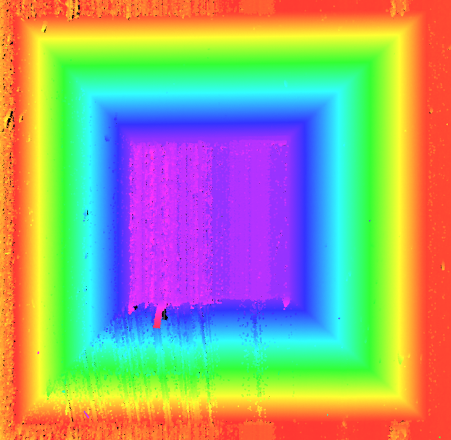
Check data in the Showing Image dropdown list to ensure that the images acquired by all laser profilers meet the following requirements.
-
The calibration target should be as close to the image center as possible.
-
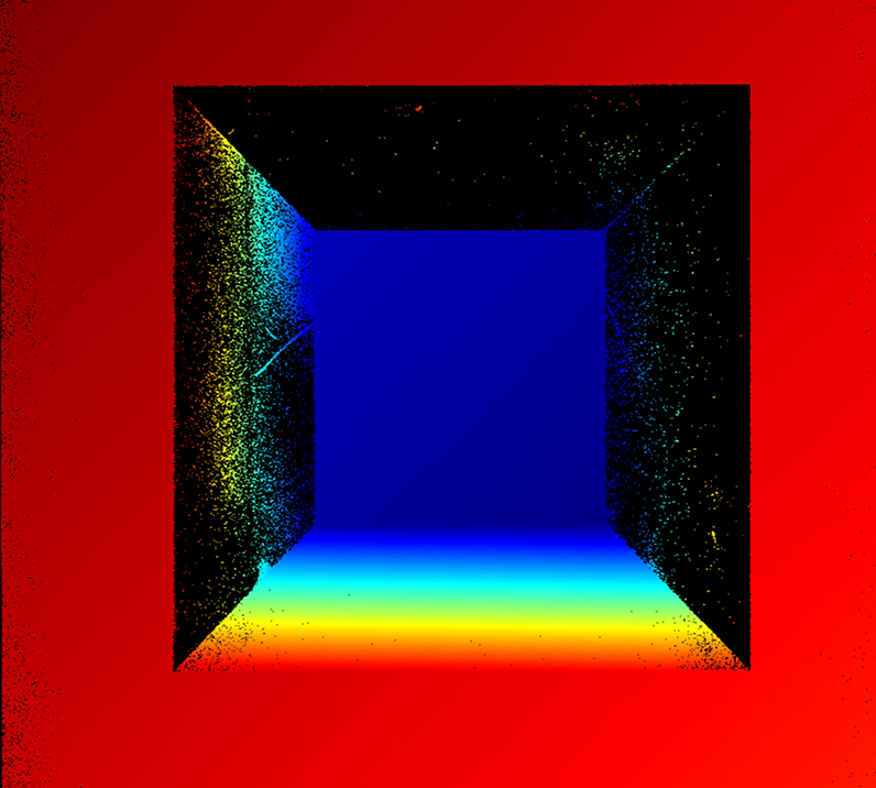
The image should contain only six feature surfaces of the calibration target, with each surface fully visible and complete.
If other surface data exists, enable Use ROI and adjust its size and location to ensure that it covers only the six feature surfaces of the calibration target. -
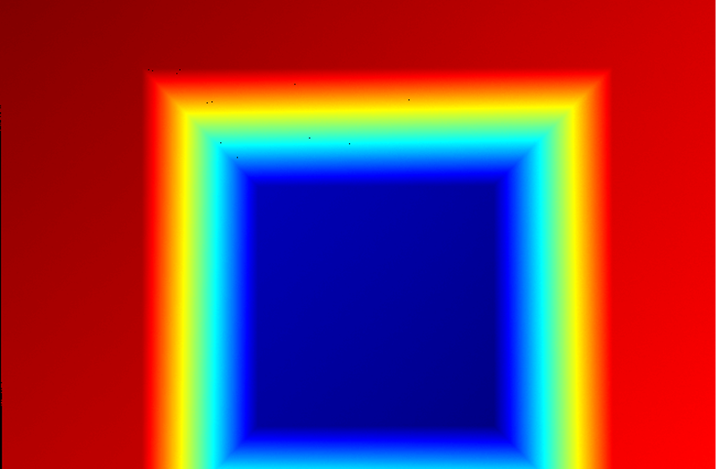
The frustum on the calibration target should face the sensor head directly without tilting around the X-, Y- or Z-axis.
-
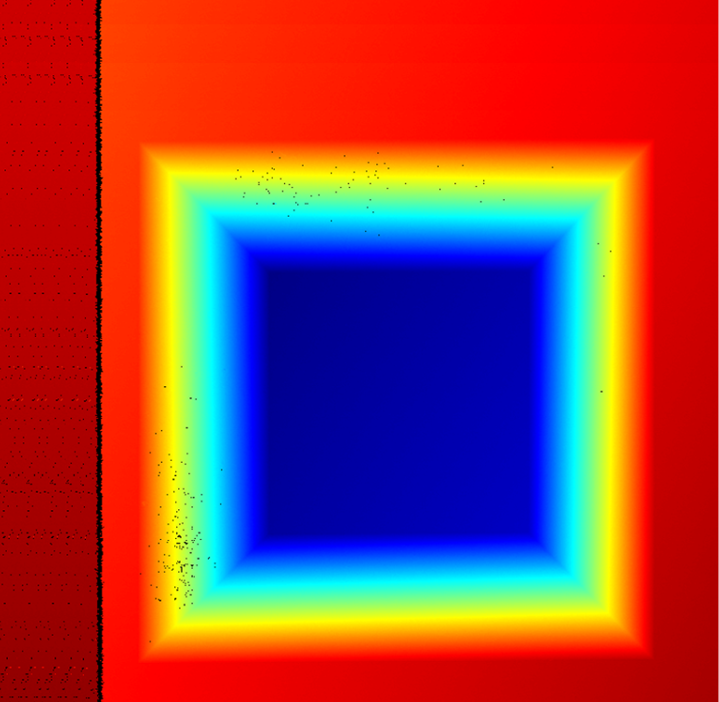
The image should have minimal noise.
Normal Severe point loss Incomplete surface Extra surface present Too much noise 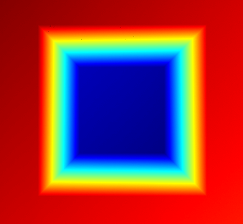
-
-
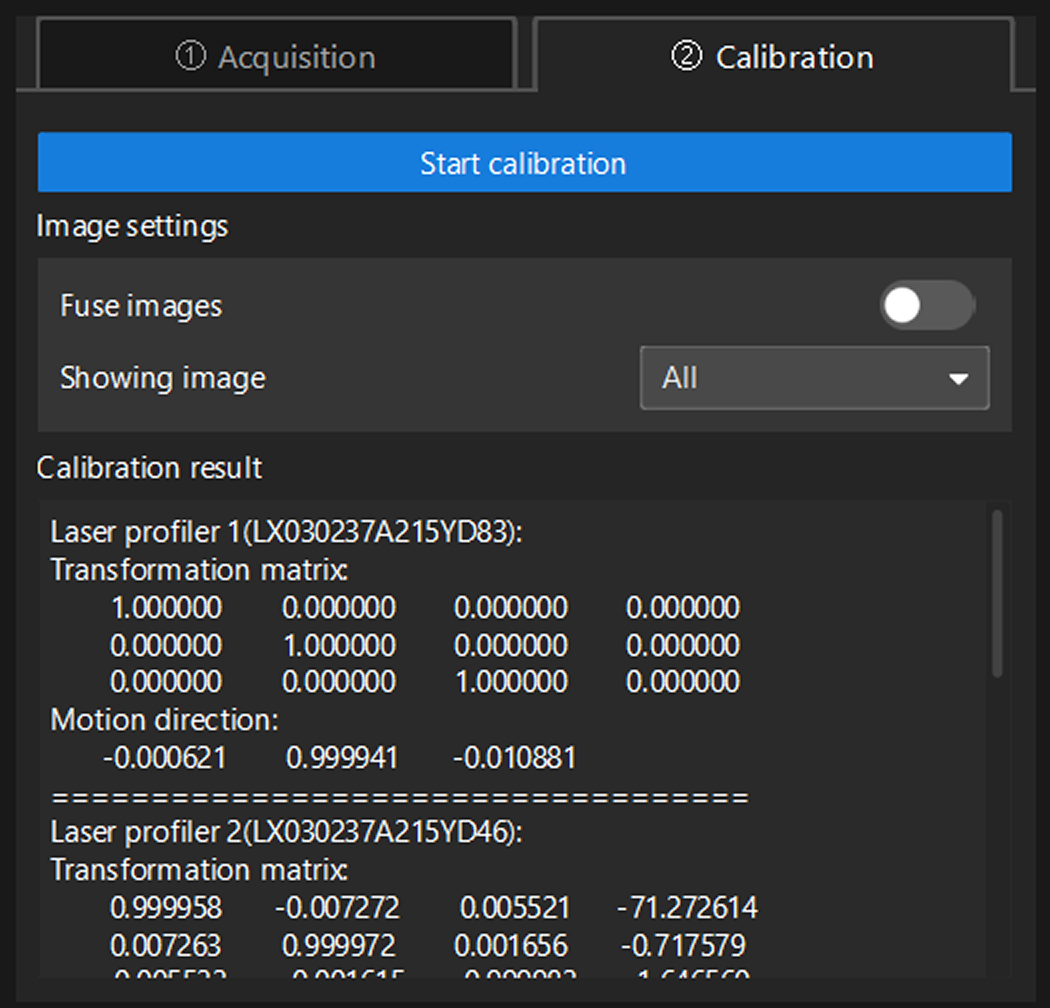
Switch to the Calibration tab and click the Start calibration button to start the multiple laser profiler calibration.
-
Check Calibration result to ensure the calibration accuracy meet your needs.
When the FOVs of laser profilers overlap, you can enable Fuse images to see if the fused images meet your expectations. -
Click the Save button to set the name and storage path of the calibration result in the pop-up window and finish the calibration.
Appendix: Interpretations of Calibration Results
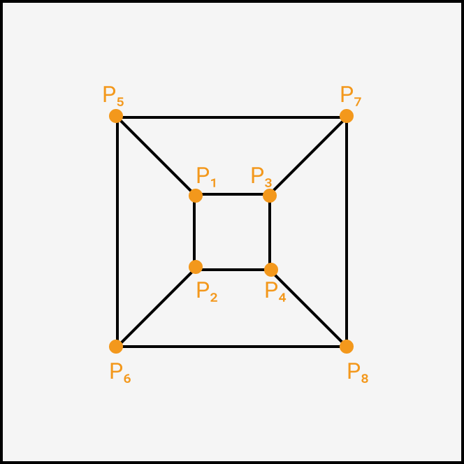
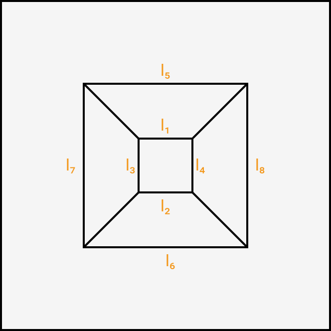
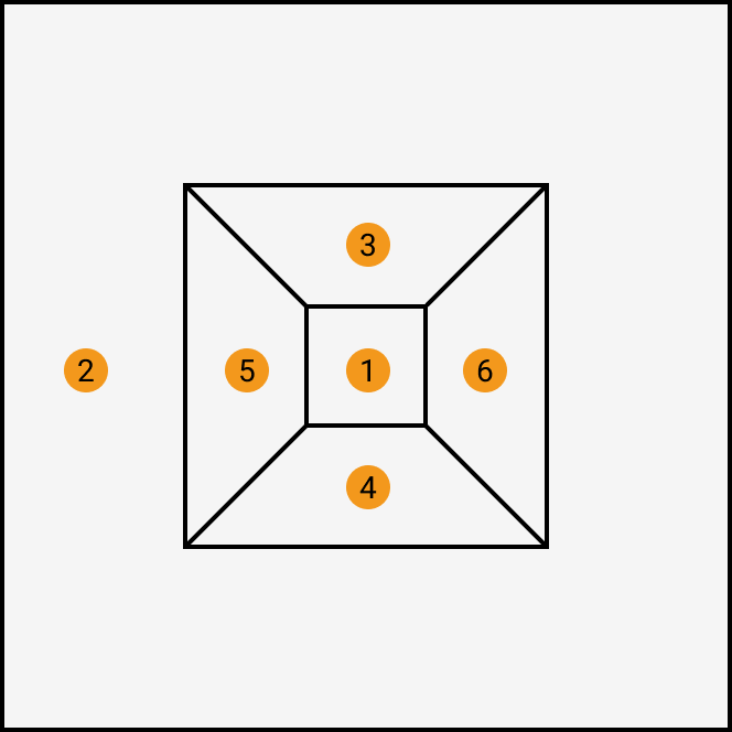
The numbering of points, lines, and planes on each frustum is defined as follows:
|
|
|
Points |
Lines |
Planes |
In image stitching, data acquired by other laser profilers will be transformed into the reference frame of the data acquired by the primary laser profiler.
| The transformation matrix and errors (excluding the “reprojection error”) are calculated relative to the primary laser profiler. |
Transformation matrix |
The translation and rotation transformations of data acquired by the laser profiler during image stitching. |
Motion direction |
The motion direction vector of the calibration target relative to the laser profiler. The reference value is (0, 1, 0), indicating that the calibration target faces the sensor head directly and moves along the positive Y-axis of the laser profiler without any rotation around the X-, Y-, or Z-axis. |
Reprojection error |
The reprojection error is generated by calculating the coordinate deviations of the frustum’s eight corners from reference coordinates. The smaller the reprojection error, the better. |
Plane-to-plane error |
The angular error between the corresponding plane normals after reference frame transformation. |
Point-to-plane error |
The error between the perpendicular distance from the point to the plane and the reference value after reference frame transformation. |
Line-to-line error |
The angular error between direction vectors of corresponding lines after reference frame transformation. |
Point-to-line error |
The error between the perpendicular distance from the point to the line and the reference value after reference frame transformation. |
Point-to-point error |
The error between the distance of corresponding points and the reference value after reference frame transformation. |