Feature Region
Feature regions define the target regions of processing during Step runs.
Set a Feature Region
In some Steps, you can adjust the feature regions directly, while in others, you need to select the Use Feature Region parameter first under “Parameters” and then adjust the feature regions.
You can set the feature region in the following ways:
-
Adjust Feature Region in Data Viewer Area
-
Adjust the position of feature region(s) intuitively and roughly
-
Adjust the size of feature region(s) intuitively and roughly
-
-
Set Feature Region Parameters in the Parameter Configuration Panel
-
Set the feature region type
-
Adjust the position of feature region(s) precisely
-
Adjust the size of feature region(s) precisely
-
Add or delete feature region(s)
-
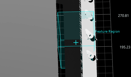
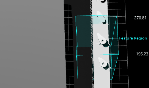
Adjust Feature Region in Data Viewer Area
This method is used to roughly adjust the feature region(s).
|
|
|
|
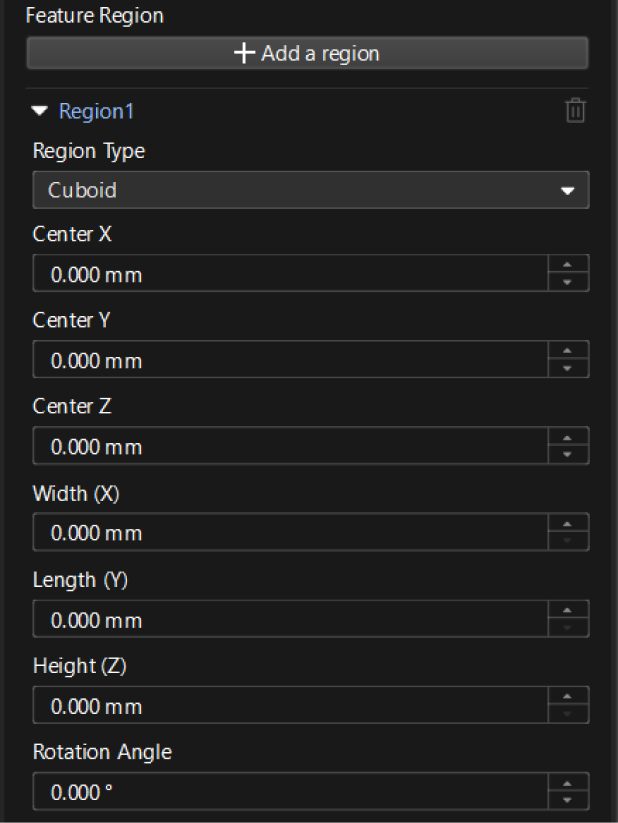
Set Feature Region Parameters in the Parameter Configuration Panel
This method is used to fine-tune a feature region. In some Steps, you can set a feature region only when the Use Feature Region option is selected.
-
Feature Region
-
Add a feature region: Click the + Add a region button to add a new feature region.
If this button is greyed out in a Step, it means that the Step does not support the creation of a new feature region or the number of created feature regions has reached the upper limit. -
Expand Region1 (Example): Click ▶ to expand Region1.
-
Region Type: You can determine the type of a feature region. The options are cuboid, cylinder, elliptic cylinder and annular cylinder.
-
Center X/Y/Z: The center position of the feature region.
-
Width (X) / Length (Z) / Height (Z): The dimensions of the feature region.
-
Rotation Angle: The angle at which the feature region rotates counterclockwise around the Z-axis of the spatial reference frame in its initial position.
-
Inner Radius: the inner radius of the annular cylinder. This parameter is visible only when the region type is set as “Annular cylinder”.
-
-
Delete a feature region: Click
 to the right of Region2 (example) to delete this feature region. If the delete icon is grayed out, the feature region cannot be deleted.
 -
Transformation Matrix: Represents the translation and rotation transformations of the feature region, in the format of [x, y, z, qw, qx, qy, qz]. This parameter is for data display only and cannot be modified.
In this matrix, the first three values represent the translation of the feature region along the X, Y, and Z axes, respectively. For example, [0.1, −0.2, 0.5] (Unit: mm) indicates a translation of 0.1 mm along the positive X-axis, -0.2 mm along the negative Y-axis, and 0.5 mm along the positive Z-axis. The last four values represent the rotation of the feature region in quaternion form. For example, [1, 0, 0, 0] indicates no rotation.
Only when the Alignment Parameter Group input port of a Step has data and a feature region or feature regions are used in the Step, the Transformation Matrix parameter will be displayed after the Step is run.
-
| The parameters of a feature region may differ from Step to Step. Please adjust the relevant parameters according to the actual display of the interface. |