Control Data Acquisition with External Device
This topic introduces how to control the laser profiler to acquire data with an external device, in order to integrate the laser profiler into a user system.
|
Relevant Input Signal Terminals
When an external device is used to control the laser profiler to acquire data, the signal wires of the external device must be connected to the corresponding input signal terminals of the controller, in order to provide the signals for controlling data acquisition to the laser profiler.
The following input signal terminals are discussed in this topic:
| No. | Name |
|---|---|
9 |
LEVELCONTROL_ENABLE |
10 |
MEASURE_START |
11 |
MEASURE_STOP |
13–16 |
Common terminal for input signal |
Overview of Data Acquisition Control with External Device
Depending on whether the LEVELCONTROL_ENABLE terminal is wired, the laser profiler supports two methods for controlling data acquisition with an external device:
-
Edge triggering: The LEVELCONTROL_ENABLE terminal is not wired. Edge triggering initiates data acquisition based on changes in signal voltage. Data acquisition is triggered when a rising or falling edge occurs, meaning the voltage instantly changes from low to high or high to low.
This method can be further divided into two types based on how data acquisition start and stop are controlled:
-
In edge triggering mode, control the start and end of data acquisition with the signals from the MEASURE_START and MEASURE_STOP terminals, respectively.
-
In edge triggering mode, control the start of data acquisition with the signal from the MEASURE_START terminal, and control the end of data acquisition with the Scan Line Count parameter.
-
-
Level triggering: The LEVELCONTROL_ENABLE terminal is wired. Level triggering initiates data acquisition based on the stable state of the signal voltage. It triggers data acquisition when the signal at the MEASURE_START terminal remains in a HIGH level state (observed on the Encoder and Input Signal Viewer), and continues until the signal changes to another state or the set number of scan lines is completed.
When the LEVELCONTROL_ENABLE terminal is wired, the MEASURE_STOP terminal becomes unavailable. This method can be further divided into two types based on how data acquisition start and stop are controlled:
-
In level triggering mode, control the start and end of data acquisition with the signals from the MEASURE_START terminal only.
-
In level triggering mode, control the start of data acquisition with the signal from the MEASURE_START terminal, and control the end of data acquisition with the Scan Line Count parameter.
-
The following provides examples of data acquisition control with an external device as described above.
-
In edge triggering mode, control the start and end of data acquisition with the signals from the MEASURE_START and MEASURE_STOP terminals, respectively.
ExampleThe target object is long, and several segments of interest are to be scanned. Based on the position of the target object, two I/O signal terminals of an PLC flexibly control the start and end of data acquisition.
-
In edge triggering mode, control the start of data acquisition with the signal from the MEASURE_START terminal, and control the end of data acquisition with the Scan Line Count parameter.
ExampleThe dimensions of the target object and the start position for scanning are fixed. When the target object arrives at the start position for scanning, it blocks the light from the optoelectronic switch, and the optoelectronic switch sends a signal to the laser profiler to start data acquisition. After scanning the set number of lines, the laser profiler stops acquiring data.
-
In level triggering mode, control the start and end of data acquisition with the signals from the MEASURE_START terminal only.
ExampleMultiple types of target objects with different dimensions are to be scanned. When the target object arrives at the start position of scanning, it starts to block the light from the optoelectronic switch, and the optoelectronic switch sends a signal to the laser profiler to start data acquisition (the signal at the MEASURE_START terminal is observed to become HIGH on the Encoder and Input Signal Viewer). The target object continues to move forward until it no longer blocks the light from the optoelectronic switch. At this moment, the optoelectronic switch sends a signal to the laser profiler to stop data acquisition (the signal at this terminal is observed to become LOW on the Encoder and Input Signal Viewer).
-
In level triggering mode, control the start of data acquisition with the signal from the MEASURE_START terminal, and control the end of data acquisition with the Scan Line Count parameter.
ExampleThe dimensions of the target object and the start position for scanning are fixed. When the target object arrives at the start position of scanning, it starts to block the light from the optoelectronic switch, and the optoelectronic switch sends a signal to the laser profiler to start data acquisition (the signal at the MEASURE_START terminal is observed to become HIGH on the Encoder and Input Signal Viewer). After scanning the set number of lines, the laser profiler stops acquiring data.
The following sections explain the above data acquisition control methods.
In edge triggering mode, control the start and end of data acquisition with the signals from the MEASURE_START and MEASURE_STOP terminals, respectively
This method controls the start and end of data acquisition with the signals from the MEASURE_START and MEASURE_STOP terminals, respectively.
Please follow the example below to connect the signal wires and provide signals for controlling data acquisition to the laser profiler.
-
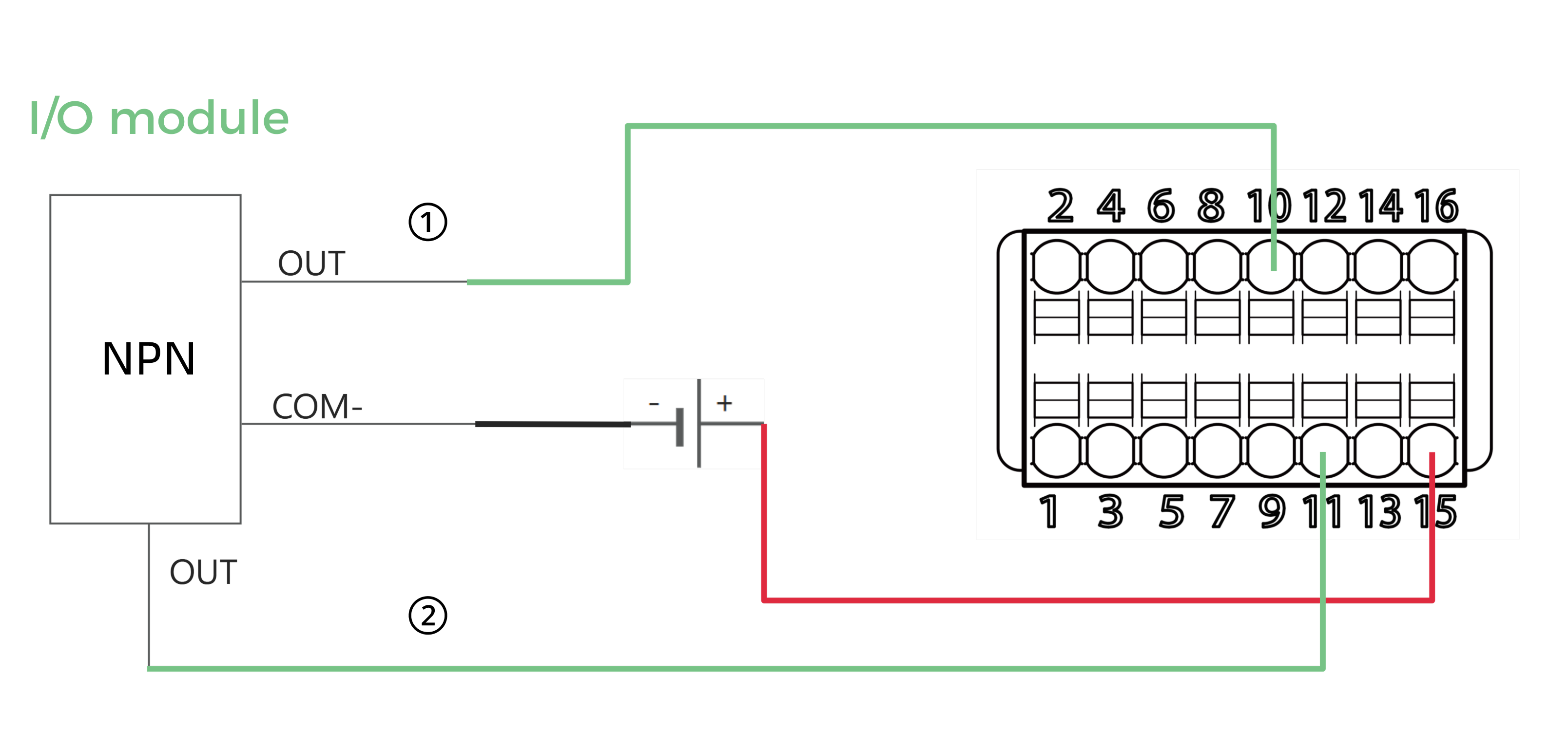
Connect the signal wires of the external device to the following terminals on the controller:
-
Connect one of the common terminals for input signal (terminals 13 to 16).
-
Connect the MEASURE_START terminal (terminal 10). Before starting data collection, use the Encoder and Input Signal Viewer to verify that the terminal signal is at a LOW level.
-
Connect the MEASURE_STOP terminal (terminal 11). Before starting data collection, use the Encoder and Input Signal Viewer to verify that the terminal signal is at a LOW level.
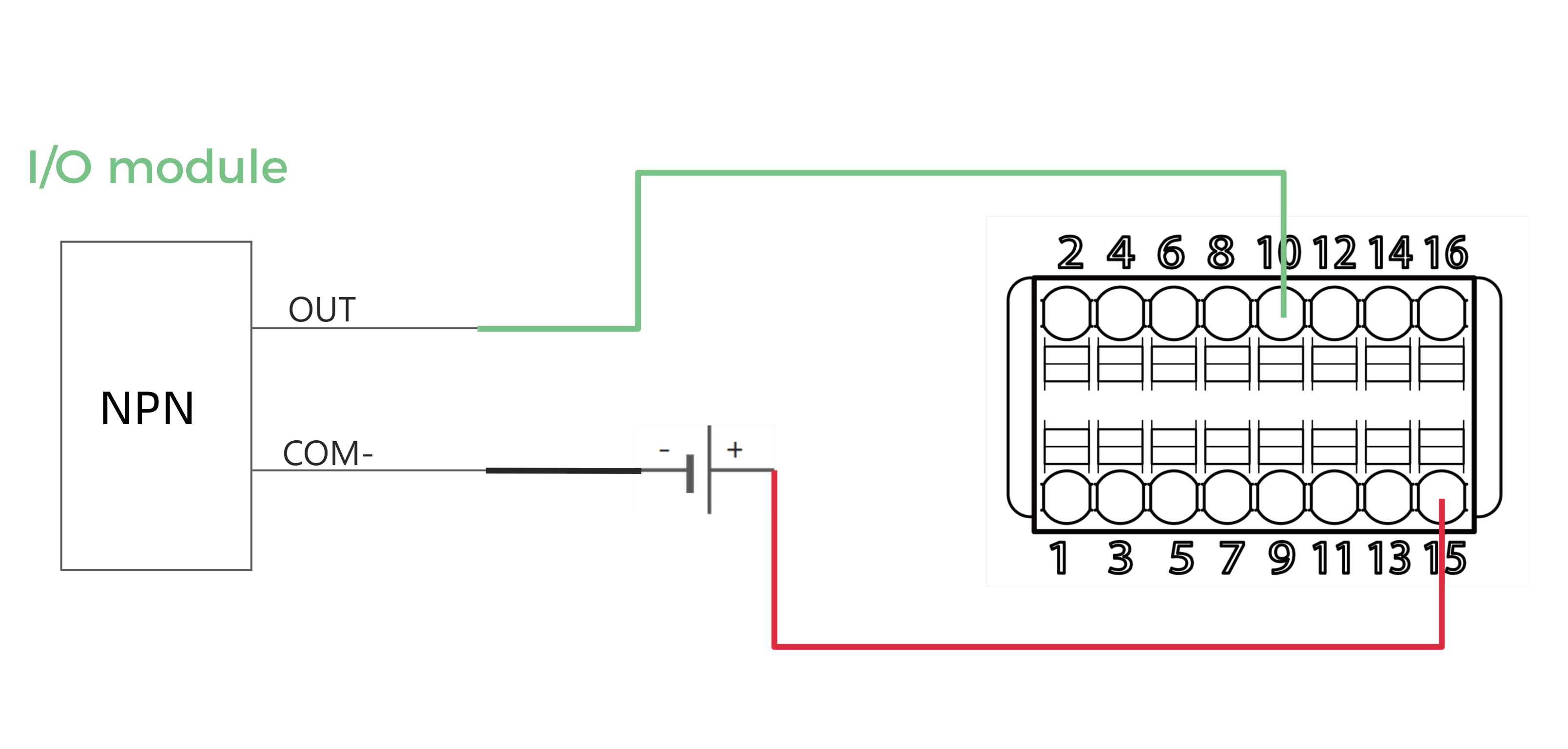
PNP NPN 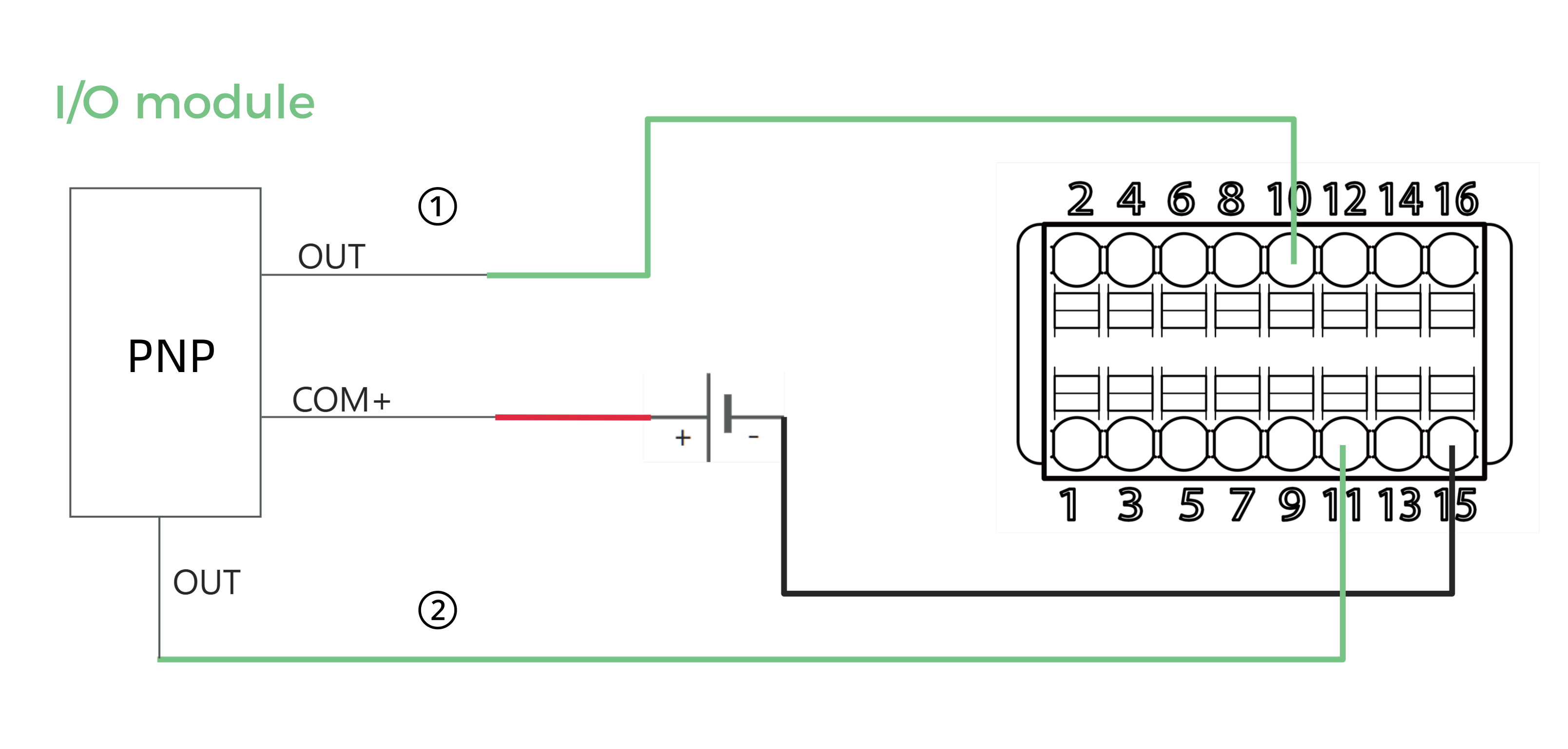
-
The terminals on the controller are numbered. Please connect the corresponding terminals according to the number.
-
The OUT signal wires ① and ② (the numbers in the diagram are for illustration purposes only) of the I/O module provide signals to the MEASURE_START and MEASURE_STOP terminals of the laser profiler respectively.
-
For the signal circuit diagrams, please refer to Signal Circuit Diagrams.
-
-
Referring to the following figure and table, adjust the logic level signal from the MEASURE_START and MEASURE_STOP terminals at the appropriate time to control the start and end of data acquisition:
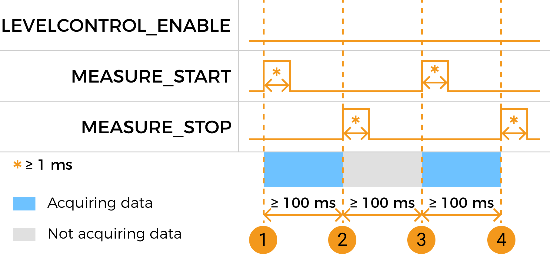
No. Data acquisition action Terminal and signal Duration requirements ①
Start a round of data acquisition
Change the logic level of the MEASURE_START terminal signal from LOW to HIGH, and then change the logic level back to LOW.
Ensure that the HIGH level of the MEASURE_START terminal signal lasts for at least 1 ms.
②
End the current round of data acquisition
Change the logic level of the MEASURE_STOP terminal signal from LOW to HIGH, and then change the logic level back to LOW.
-
Ensure that the rising edge of the MEASURE_STOP terminal and the previous rising edge of the MEASURE_START terminal are separated by at least 100 ms.
-
Ensure that the HIGH level of the MEASURE_STOP terminal signal lasts for at least 1 ms.
③
Start the next round of data acquisition
Change the logic level of the MEASURE_START terminal signal from LOW to HIGH, and then change the logic level back to LOW.
-
Ensure that the rising edge of the MEASURE_START terminal and the previous rising edge of the MEASURE_STOP terminal are separated by at least 100 ms.
-
Ensure that the HIGH level of the MEASURE_START terminal signal lasts for at least 1 ms.
④
End the current round of data acquisition
Change the logic level of the MEASURE_STOP terminal signal from LOW to HIGH, and then change the logic level back to LOW.
-
Ensure that the rising edge of the MEASURE_STOP terminal and the previous rising edge of the MEASURE_START terminal are separated by at least 100 ms.
-
Ensure that the HIGH level of the MEASURE_STOP terminal signal lasts for at least 1 ms.
-
In edge triggering mode, control the start of data acquisition with the signal from the MEASURE_START terminal, and control the end of data acquisition with the Scan Line Count parameter
This method controls the start of data acquisition with the signal from the MEASURE_START terminal, and control the end of data acquisition with the Scan Line Count parameter.
Please follow the example below to connect the signal wires and provide signals for controlling data acquisition to the laser profiler.
-
Connect the signal wires of the external device to the following terminals on the controller:
-
Connect one of the common terminals for input signal (terminals 13 to 16).
-
Connect the MEASURE_START terminal (terminal 10). Before starting data collection, use the Encoder and Input Signal Viewer to verify that the terminal signal is at a LOW level.
PNP NPN 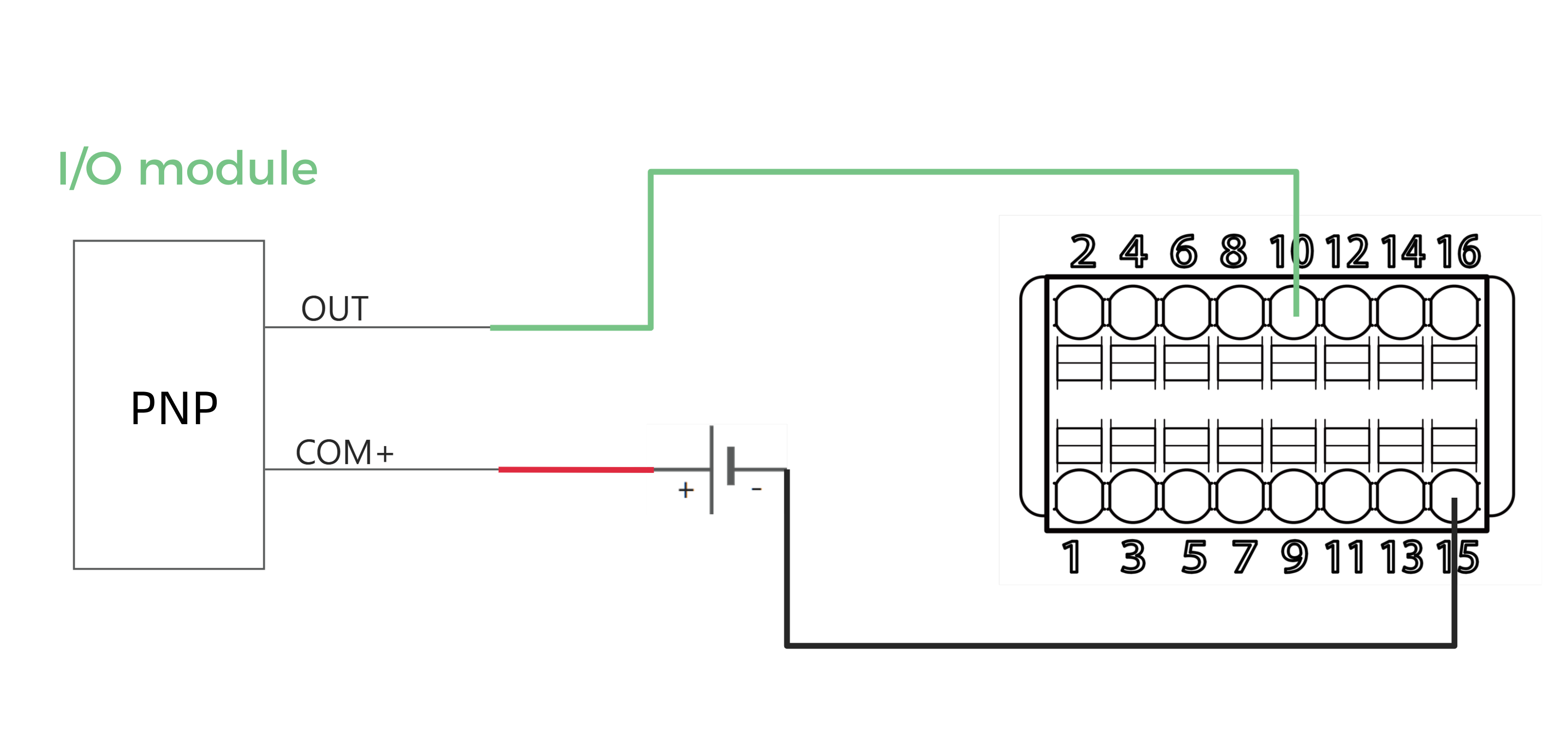
-
The terminals on the controller are numbered. Please connect the corresponding terminals according to the number.
-
This method does not use the signal from the MEASURE_STOP terminal. Therefore you do not need to connect the MEASURE_STOP terminal (terminal 11).
-
For the signal circuit diagrams, please refer to Signal Circuit Diagrams.
-
-
Referring to the following figure and table, set an appropriate value for the Scan Line Count parameter and adjust the logic level signal from the MEASURE_START terminal at the appropriate time to control the start and end of data acquisition:
No. Data acquisition action Terminal and signal Duration requirements ①
Start a round of data acquisition
Change the logic level of the MEASURE_START terminal signal from LOW to HIGH, and then change the logic level back to LOW.
Ensure that the HIGH level of the MEASURE_START terminal signal lasts for at least 1 ms.
②
End the current round of data acquisition
Data acquisition ends automatically when the laser profiler finishes acquiring the number of profiles set in the Scan Line Count parameter.
-
③
Start the next round of data acquisition
Change the logic level of the MEASURE_START terminal signal from LOW to HIGH, and then change the logic level back to LOW.
-
Ensure that interval between the two rising edges of the MEASURE_START terminals is long enough.
The required interval depends on Scan Line Count and the scan rate. When Scan Line Count and the scan rate are at their maximum values, the required interval can be up to 3 to 4 s. -
Ensure that the HIGH level of the MEASURE_START terminal signal lasts for at least 1 ms.
④
End the current round of data acquisition
Data acquisition ends automatically when the laser profiler finishes acquiring the number of profiles set in the Scan Line Count parameter.
-
-
In level triggering mode, control the start and end of data acquisition with the signals from the MEASURE_START terminal only.
This method controls the start and end of data acquisition with the signals from the MEASURE_START terminal only.
Please follow the example below to connect the signal wires and provide signals for controlling data acquisition to the laser profiler.
-
Connect the signal wires of the external device to the following terminals on the controller:
-
Connect one of the common terminals for input signal (terminals 13 to 16).
-
Connect the LEVELCONTROL_ENABLE terminal (terminal 9). Use the Encoder and Input Signal Viewer to verify that the terminal signal remains at a HIGH level.
-
Connect the MEASURE_START terminal (terminal 10). Before starting data collection, use the Encoder and Input Signal Viewer to verify that the terminal signal is at a LOW level.
PNP NPN 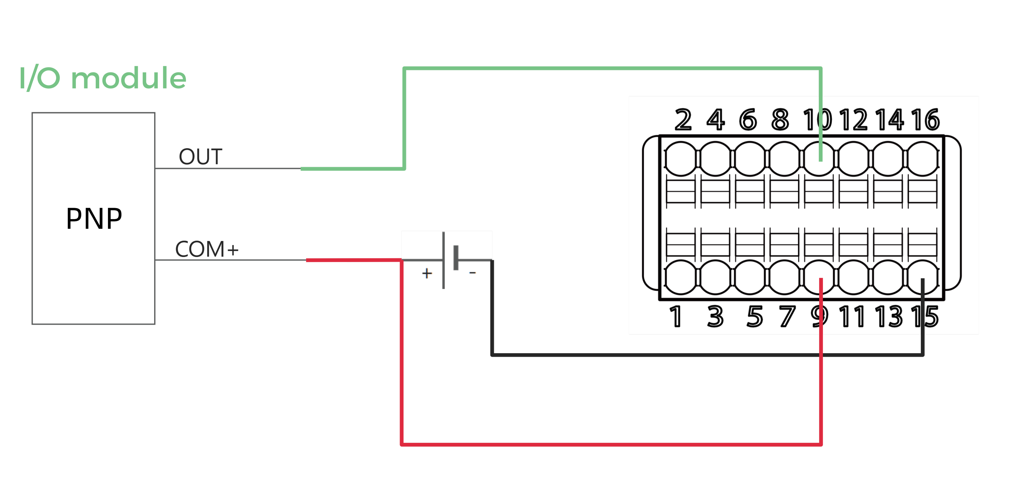
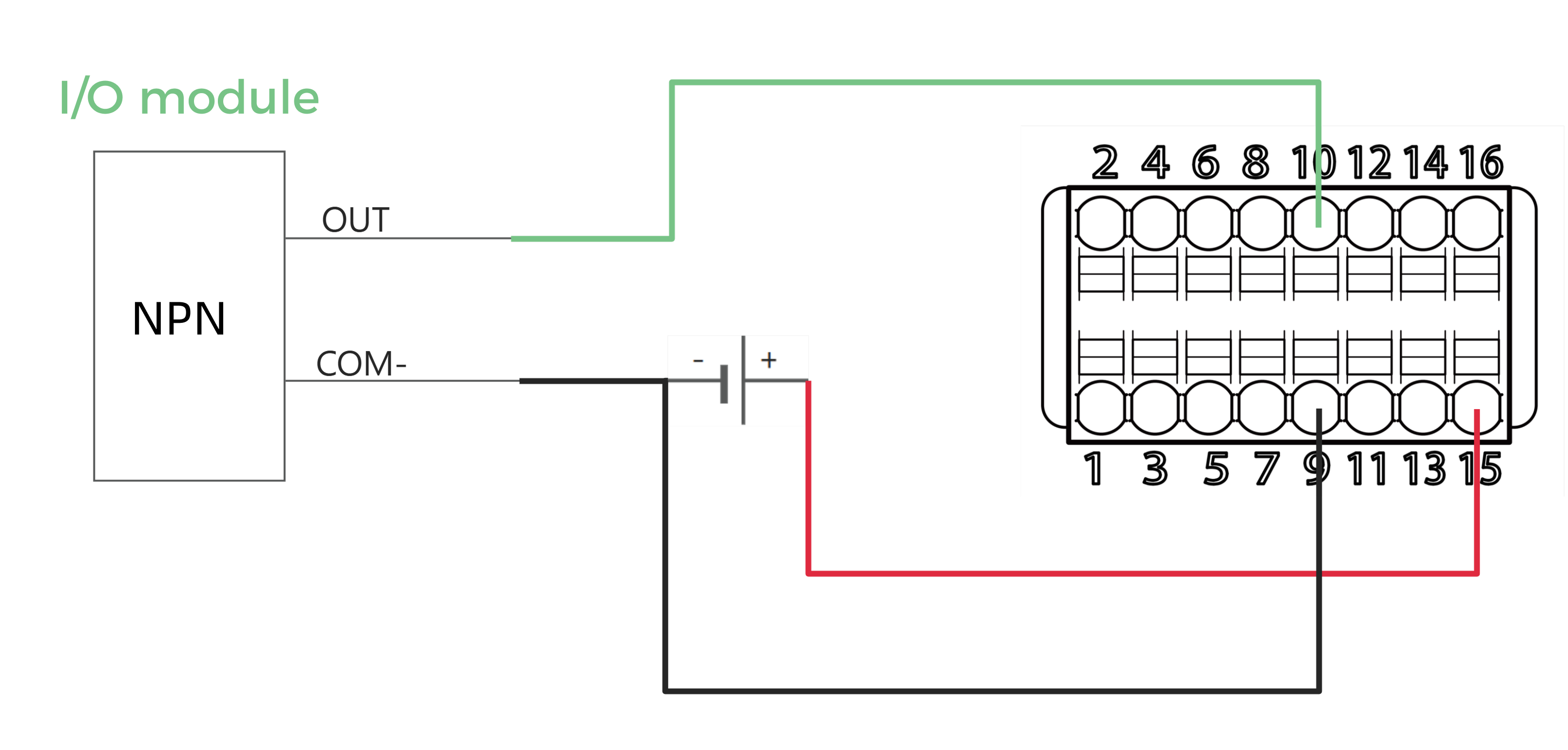
-
The terminals on the controller are numbered. Please connect the corresponding terminals according to the number.
-
For the signal circuit diagrams, please refer to Signal Circuit Diagrams.
-
-
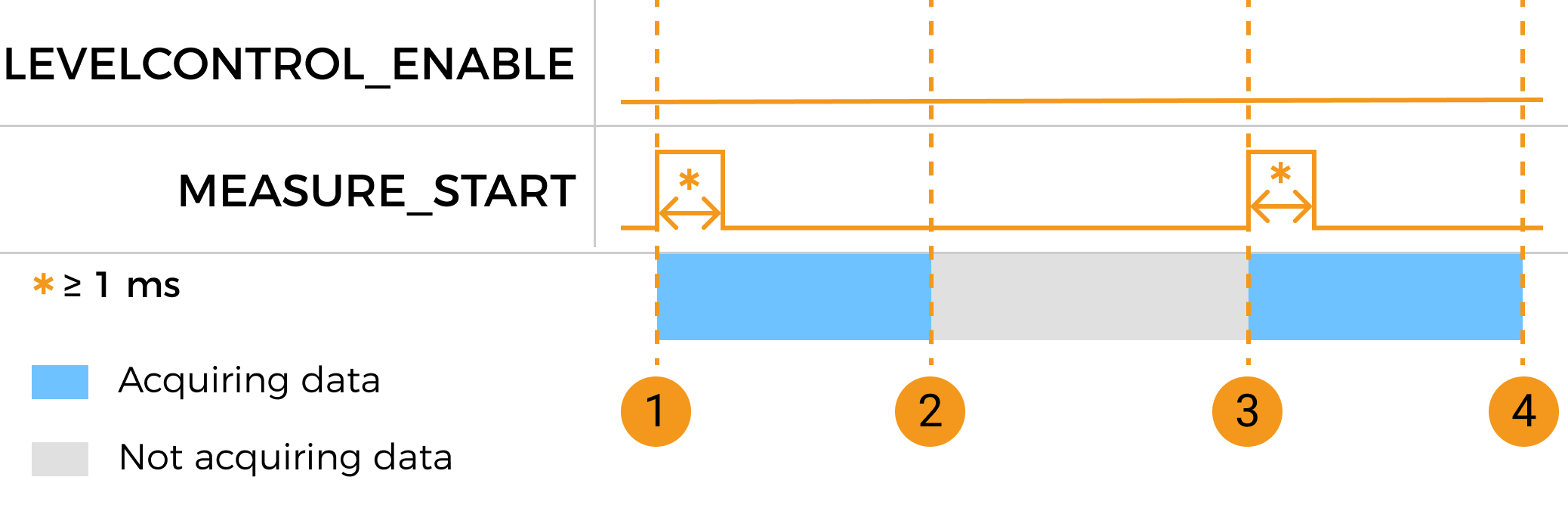
Referring to the following figure and table, adjust the logic level signal from the MEASURE_START terminal at the appropriate time to control the start and end of data acquisition:
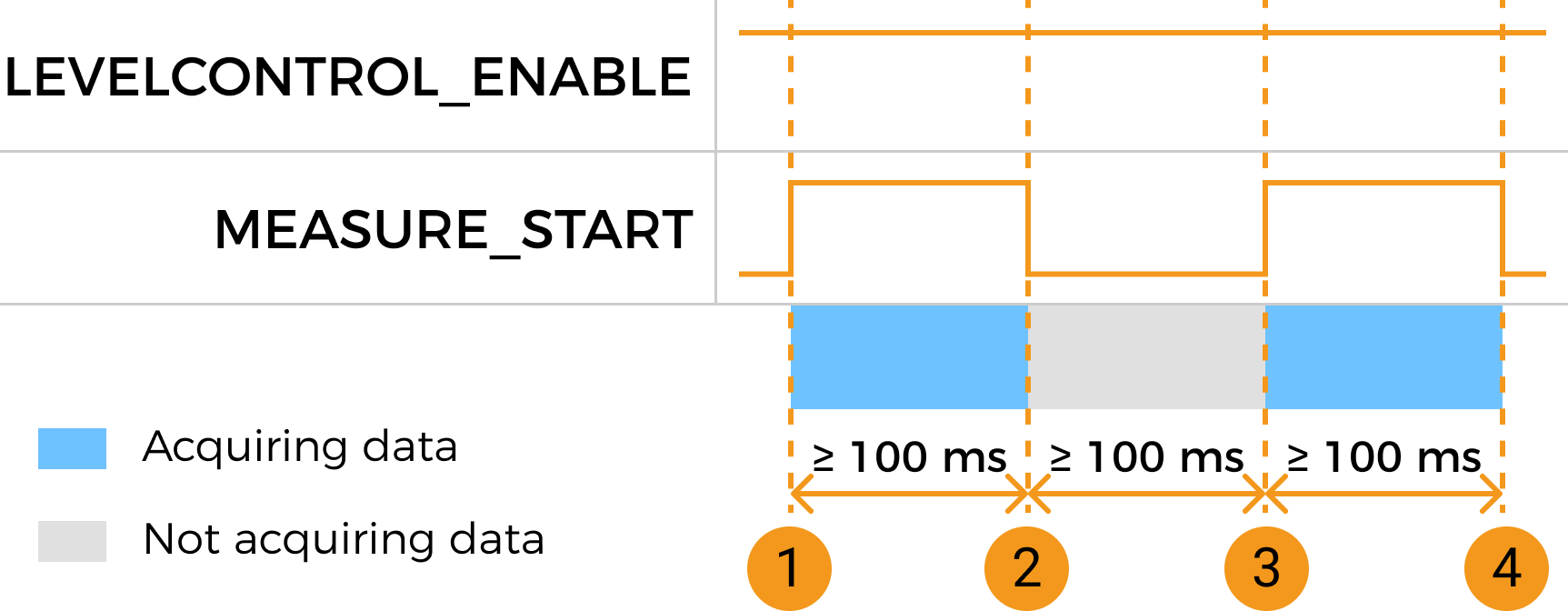
No. Data acquisition action Terminal and signal Duration requirements ①
Start a round of data acquisition
Change the logic level of the MEASURE_START terminal signal from LOW to HIGH.
Ensure that the HIGH level of the MEASURE_START terminal signal lasts for at least 100 ms.
②
End the current round of data acquisition
Change the logic level of the MEASURE_START terminal signal from HIGH to LOW.
-
③
Start the next round of data acquisition
Change the logic level of the MEASURE_START terminal signal from LOW to HIGH.
-
Ensure that the LOW level of the MEASURE_START terminal signal lasts for at least 100 ms.
-
Ensure that the HIGH level of the MEASURE_START terminal signal lasts for at least 100 ms.
④
End the current round of data acquisition
Change the logic level of the MEASURE_START terminal signal from HIGH to LOW.
-
-
In level triggering mode, control the start of data acquisition with the signal from the MEASURE_START terminal, and control the end of data acquisition with the Scan Line Count parameter
This method controls the start of data acquisition with the signal from the MEASURE_START terminal, and control the end of data acquisition with the Scan Line Count parameter.
Please follow the example below to connect the signal wires and provide signals for controlling data acquisition to the laser profiler.
-
Connect the signal wires of the external device to the following terminals on the controller:
-
Connect one of the common terminals for input signal (terminals 13 to 16).
-
Connect the LEVELCONTROL_ENABLE terminal (terminal 9). Use the Encoder and Input Signal Viewer to verify that the terminal signal remains at a HIGH level.
-
Connect the MEASURE_START terminal (terminal 10). Before starting data collection, use the Encoder and Input Signal Viewer to verify that the terminal signal is at a LOW level.
PNP NPN
-
The terminals on the controller are numbered. Please connect the corresponding terminals according to the number.
-
For the signal circuit diagrams, please refer to Signal Circuit Diagrams.
-
-
Referring to the following figure and table, set an appropriate value for the Scan Line Count parameter and adjust the logic level signal from the MEASURE_START terminal at the appropriate time to control the start and end of data acquisition:
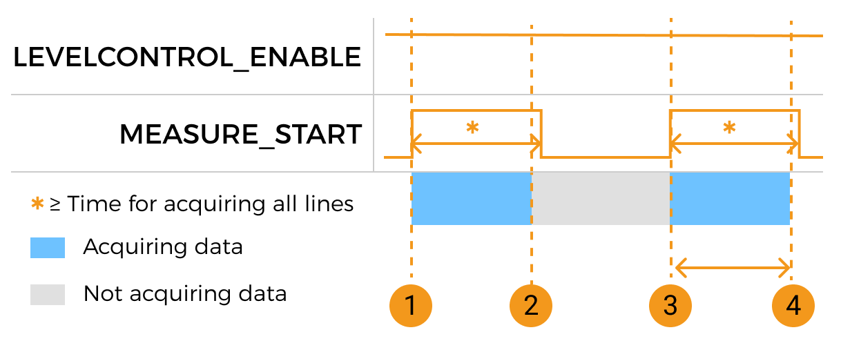
No. Data acquisition action Terminal and signal Duration requirements ①
Start a round of data acquisition
Change the logic level of the MEASURE_START terminal signal from LOW to HIGH, and then change the logic level back to LOW.
Ensure that the HIGH-level duration of the MEASURE_START terminal signal exceeds the time required for the laser profiler to complete the acquisition of all lines, as set by the Scan Line Count parameter.
②
End the current round of data acquisition
Data acquisition ends automatically when the laser profiler finishes acquiring all profile lines.
-
③
Start the next round of data acquisition
Change the logic level of the MEASURE_START terminal signal from LOW to HIGH.
Ensure that the HIGH-level duration of the MEASURE_START terminal signal exceeds the time required for the laser profiler to complete the acquisition of all lines, as set by the Scan Line Count parameter.
④
End the current round of data acquisition
Data acquisition ends automatically when the laser profiler finishes acquiring all profile lines.
-
Next Steps
After selecting the control logic and connecting the hardware, please refer to Workflow of Triggering Data Acquisition and complete the other steps in order to trigger data acquisition with externally input signals.