Cable Routing and Wiring Guidelines for Laser Profiler
This topic introduces the cable routing and wiring guidelines for the laser profiler, including the sensor head and controller.
Cable Routing Guidelines for Laser Profiler
Bending Radius Guidelines
Definition
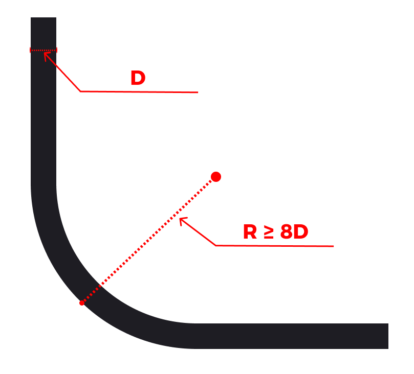
Bending radius refers to the distance from the outer side of the cable to the center of the bend when the cable is bent.
Requirements
-
The bending radius should not be less than 8 times the outer diameter of the cable (8D). You must strictly adhere to the guidelines to avoid excessive bending.
-
It is recommended that the bending radius of the laser profiler cable should not be less than 6 cm.
-
Pay special attention to the connectors of the sensor head and the controller. The distance from the cable’s M12 connector to the bending point should be greater than 13 cm.
Example
Cable Securing Guidelines
Definition
Cable securing refers to the use of proper support and fixation measures to ensure that the cable remains stable and reliable during installation and operation, unaffected by movement, stretching, or wear.
Requirements
A fixed support point should be set between the cable’s M12 connector and the cable’s bending point to securely fasten the cable. This prevents stress on the M12 connector during cable or laser profiler movement, reducing the risk of loosening. In addition, the distance from the M12 connector to the fixed support point should be no less than 13 cm.
Example

In addition, if cable bundling is required, please follow the following requirements:
-
The bundled cables should be neatly arranged, with a tidy appearance and no damage to the outer insulation.
-
When bundling the cables with cable ties, ensure that the heads of the cable ties are facing the same direction. Cable ties at the same position should be aligned on the same horizontal line, and the heads of the cable ties should be trimmed evenly.
-
When bundling the cables, the spacing between the cable ties should be 3 to 4 times the diameter of the cable bundle, and the ties should be evenly distributed.
Cable Protection Guidelines
Definition
Cable protection refers to the use of various protective measures to ensure that the cable is protected from damage caused by external environments or mechanical stress during installation and use.
Requirements
-
You should avoid crossing cables and prevent cables from coming into contact with sharp objects to reduce wear and extend the cable’s service life.
-
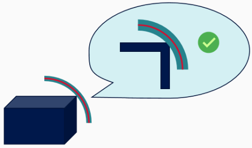
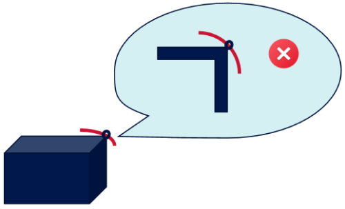
In areas prone to damage, use protective conduits to further protect the cables from physical damage. At sharp corners, use spiral cable wraps for protection, but avoid using cable ties for securing, as this may cause wear on both the cable wrap and the cable itself.
Example
| Correct | Incorrect |
|---|---|
|
|
Routing Requirements for Cables inside Dresspack or Track Chain
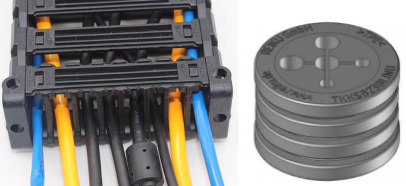
During cable routing, dresspack and drag chain (such as track chain) are two common cable protection devices. When routing cables inside a dresspack or track chain, adhere to the following requirements.
|
-
Avoid fixing the cables inside
Inside the dresspack or track chain, you should avoid fixing the cables to the internal structure to ensure they have sufficient freedom to move and bend, preventing any restriction of their normal movement. Please refer to the figure below for specific securing methods.
-
Fix the cables at the entrance to prevent friction
Secure the cables at the entrance of the dresspack or track chain to prevent friction between cables.
-
Ensure that a part of the track chain does not move with the laser profiler
The general requirement is that at least 3 to 4 sections of the track chain do not move with the laser profiler.
-
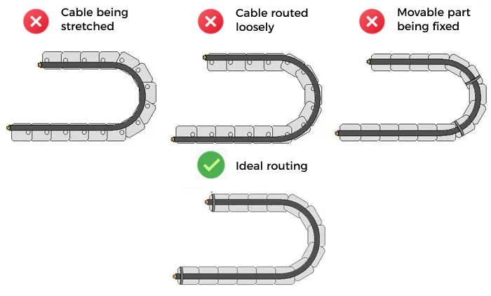
Avoid subjecting the cables in the track chain to additional tension
When routing cables inside the track chain, you should avoid subjecting the cables to excessive additional tension. The cables should not be pulled too tight (as shown in the left image), nor should they be too loose (as shown in the right image). Pulling the cables too tight or too loose can cause friction with the inner walls of the track chain, leading to wear on the protective sleeve. Additionally, excessive looseness can increase the risk of entanglement. In addition, if the moving parts of the cables are fixed, bending stress cannot be dispersed and absorbed, leading to stress concentration at the fixed points. Therefore, the cables should be fixed only at both ends of the track chain.
-
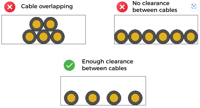
Prevent interference between cables inside the track chain
When routing cables inside the track chain, you should avoid overlapping cables and implement horizontal routing to prevent interference between cables. When implementing horizontal routing, ensure there is enough clearance between the cables. Inside the track chain, the clearance between cables should be at least 10% of the cable diameter to ensure that each cable has enough space and does not come into contact or friction with others.
-
Avoid cable knots and tangling inside the corrugated tube
When routing cables inside the corrugated tube, ensure that the cables do not knot or tangle, to prevent friction or damage caused by cable entanglement.
Wiring Guidelines for Laser Profiler
To ensure the proper use of the laser profiler, you need to establish the correct wiring, which primarily includes the connections between the sensor head and the controller, the controller and the DIN rail power supply, the controller and external I/O devices, and the controller and the encoder.
Connect the Sensor Head and Controller
Refer to the hardware user manual and use the Sensor-Head-to-Controller cable provided in the package to Connect Sensor Head and Controller. When wiring, the following requirements should also be observed.
Considering the requirements for the disassembly and installation of cable connectors, the reserved space for the cable connectors during laser profiler installation should meet the following requirements:
-
Straight connector: H1 ≥ 130 mm
-
Right-angle connector: H2 ≥ 110 mm; L ≥ 70 mm
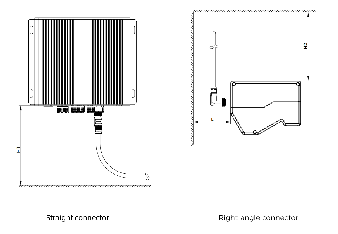
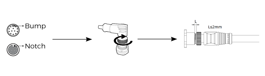
| The right-angle connector of the Sensor-Head-to-Controller cable is used to connect the sensor head, while the straight connector is used to connect the controller. The connectors of the cables are all M12 connectors. |
In addition, when installing the M12 connector, rotate the cable’s M12 connector while tightening the nut, pushing it forward until fully tightened to ensure the connection remains secure. After tightening the M12 connector, the thread gap (L) should not exceed 2 mm.
Connect the Controller and DIN Rail Power Supply
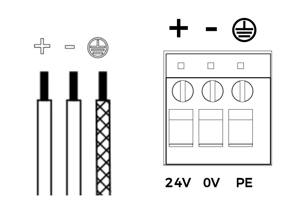
Refer to the hardware user manual and use the controller’s DC power cable provided in the package to Connect Controller and DIN Rail Power Supply. When wiring, the following requirements should also be observed.
-
Ensure that the pigtail wires of the controller’s DC power cable is inserted into the terminal block with a depth of at least 9 mm.
-
After completing the ground wire connection, use a multimeter in the resistance mode to measure the resistance between the machine ground point and the controller and sensor head test points. Ensure that the ground resistance does not exceed 1Ω.
The resistance test points for the controller and sensor head are shown in the diagram below (① and ②).

Connect the Controller with the External IO Device and Encoder
The laser profiler supports external triggering, that is, using the signal input from an external device to trigger each round of data acquisition. In addition, the laser profiler supports triggering each line scan through the encoder signal. To trigger the laser profiler correctly, you need to establish the proper connections between the controller, external IO devices, and the encoder.
Refer to the hardware user manual and connect wires to signal terminals. When wiring, the following requirements should also be observed.
Connect Wires to Input Signal Terminals
By connecting the signal wires of the external device to the corresponding input signal terminals of the controller, you can control data acquisition of the laser profiler with the external device.
The laser profiler supports multiple methods of controlling data acquisition with an external device. The connection requirements for the input signal terminals vary depending on the method of controlling data acquisition with an external device. For details, please refer to Control Data Acquisition with External Device.
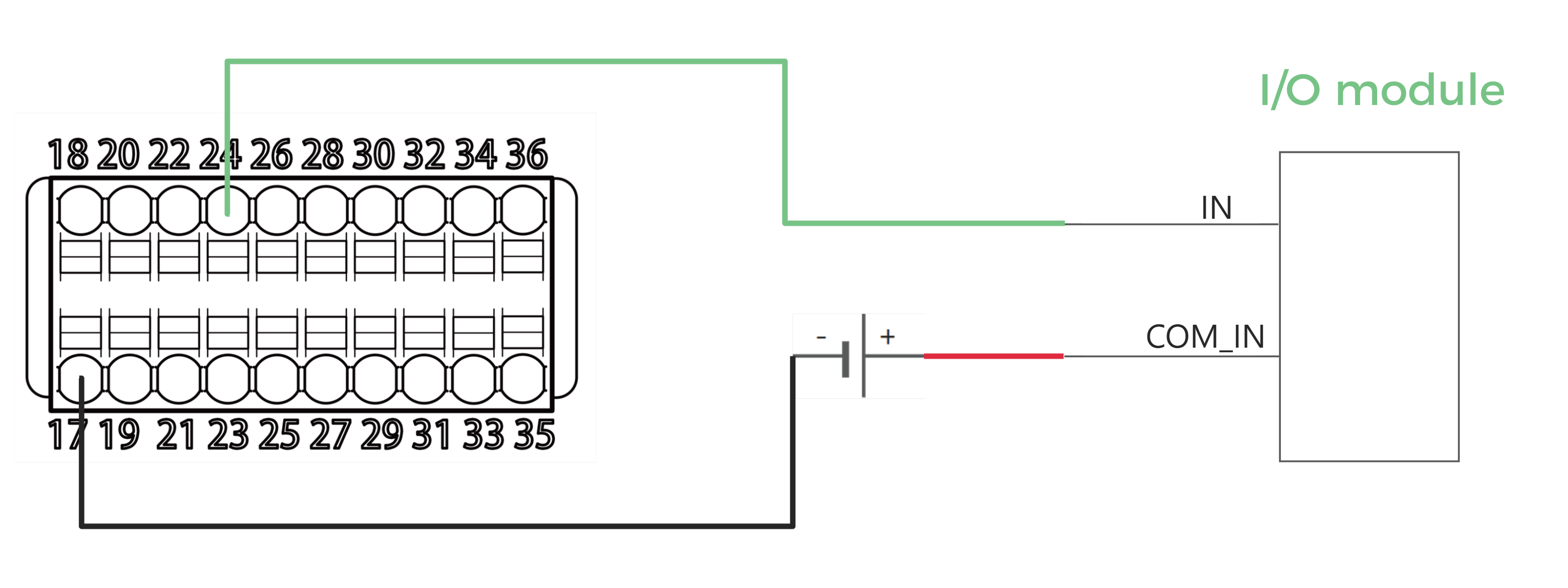
Connect Wires to Output Signal Terminals
By connecting the signal wires of the external device to the corresponding output signal terminals of the controller, you can output the laser profiler’s data acquisition status signal or custom signals (defined via API) to the external device.
Please refer to the following connection diagram to connect the controller’s output signal terminals.
|
Connect Wires to Encoder Signal Terminals
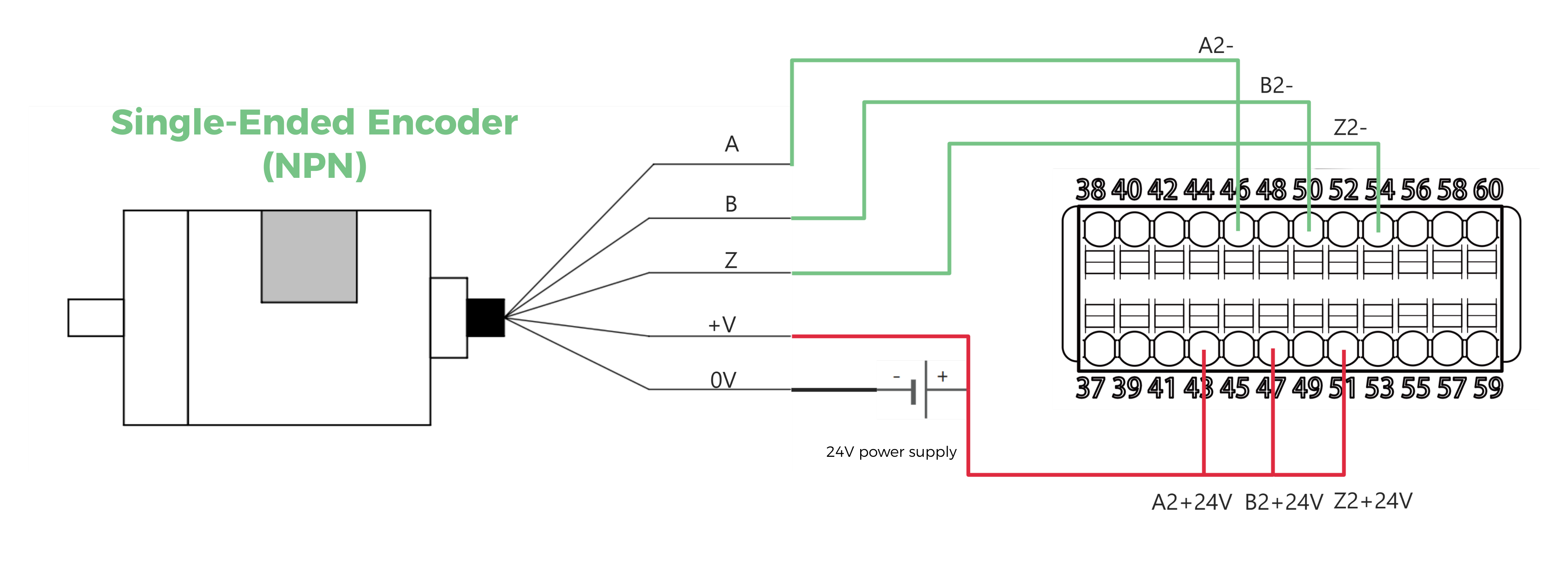
The laser profiler supports triggering each line scan through the encoder signal. The laser profiler supports connecting signals from both differential encoders and single-ended encoders to the encoder signal terminals of the controller.
|
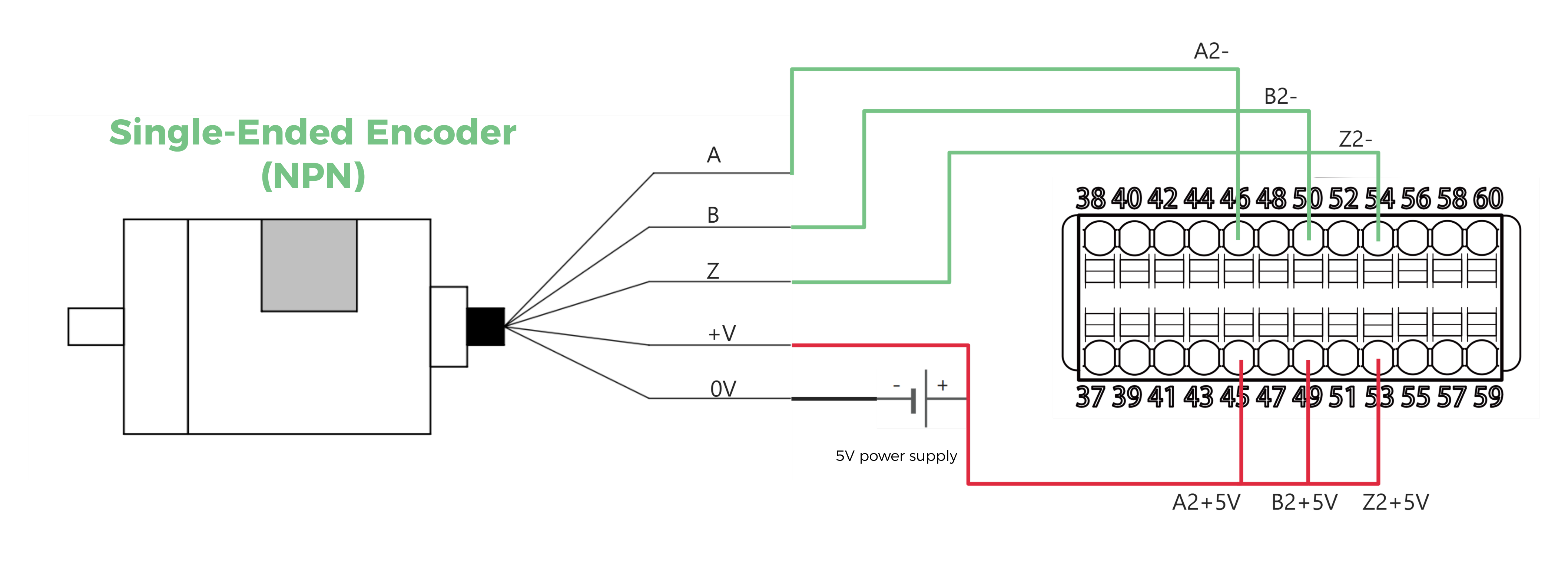
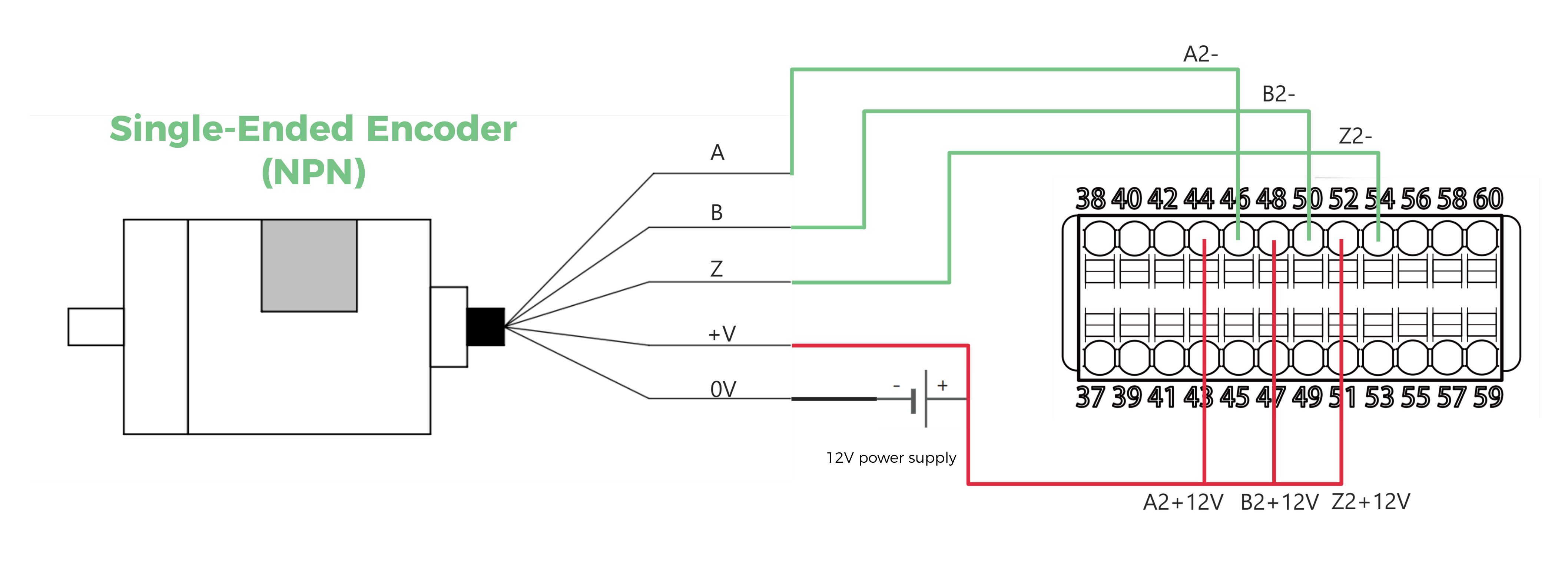
Single-ended encoder
Please refer to the following diagrams to connect the single-ended encoder wires to the encoder signal terminals of the controller.
| Signal source type | Power supply voltage | Connection diagram |
|---|---|---|
NPN |
5 V |
|
12 V |
|
|
24 V |
|
|
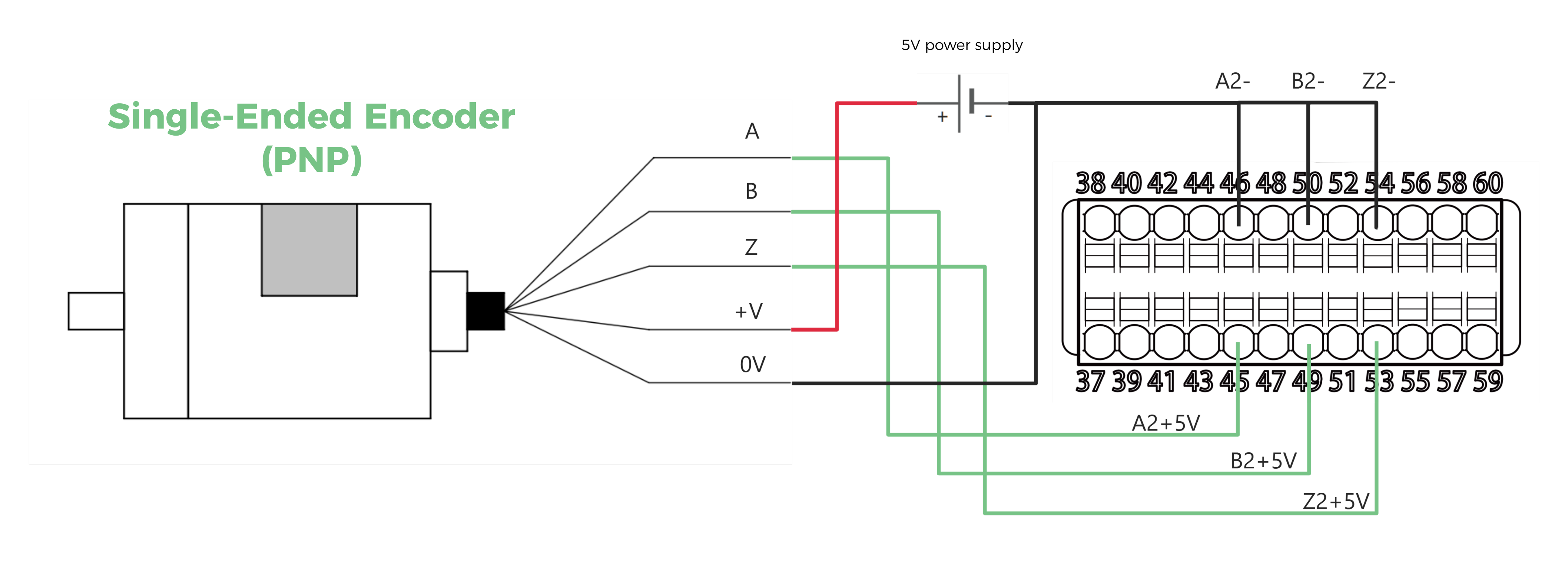
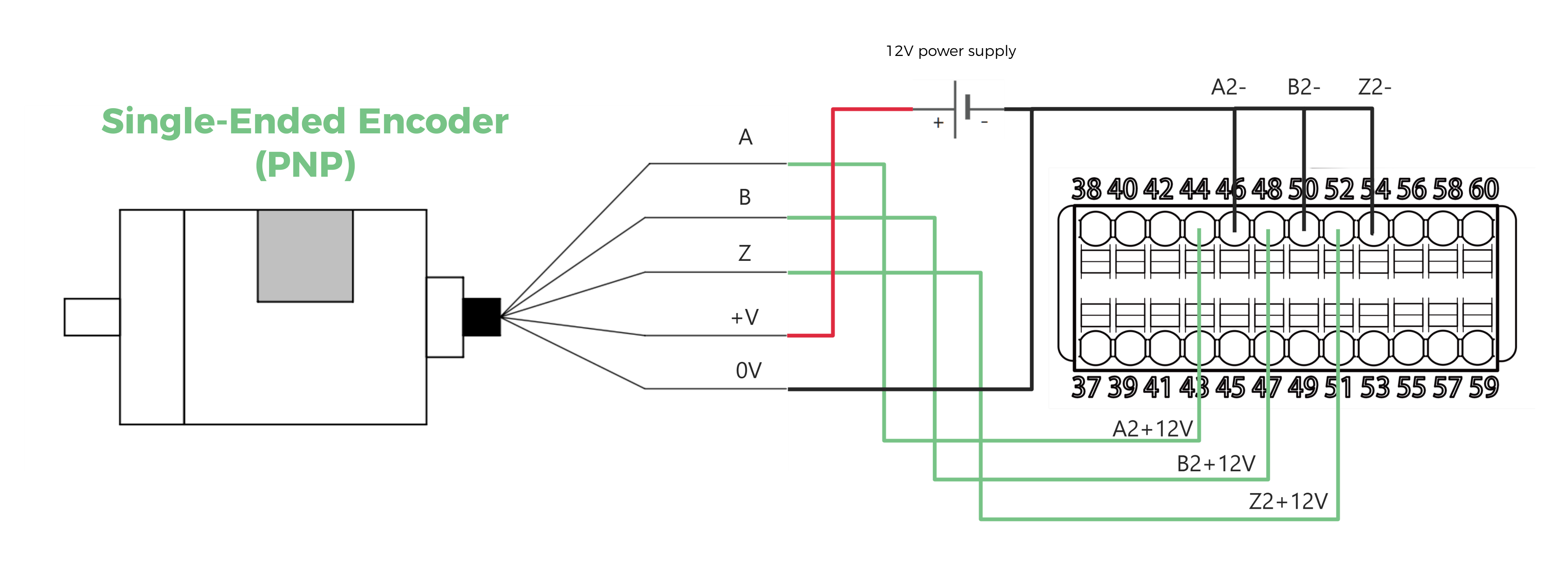
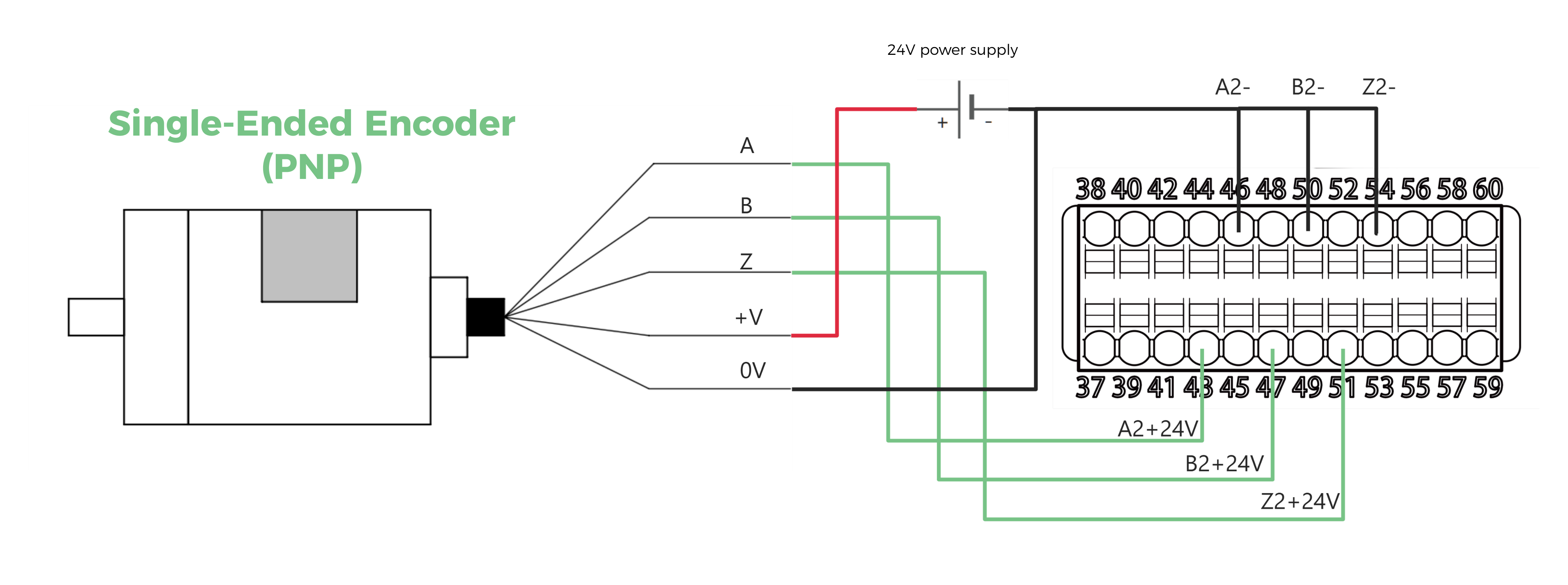
PNP |
5 V |
|
12 V |
|
|
24 V |
|
|
Differential encoder
Please refer to the following diagrams to connect the differential encoder wires to the encoder signal terminals of the controller.
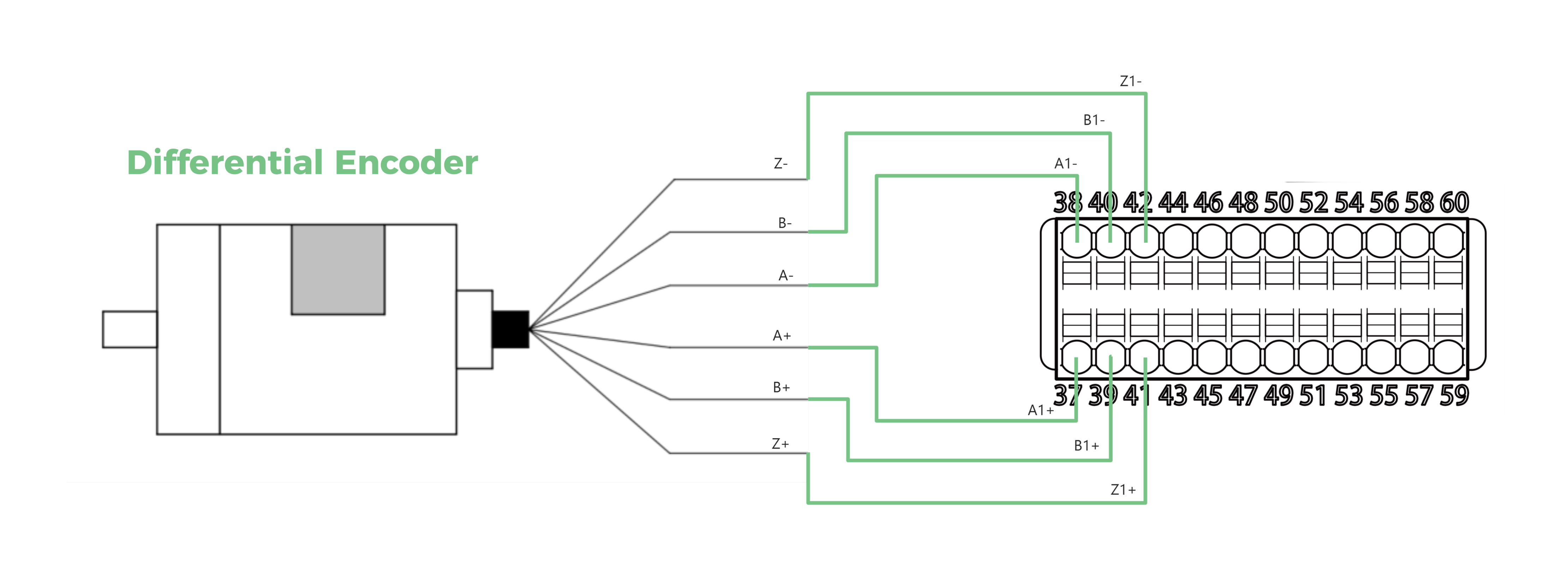
|