Calibration Target Design and Machining Guide
In industrial production, multiple laser profilers may be deployed together to scan the target object, thereby expanding the field of view and eliminating visual blind spots.
When calibrating multiple laser profilers, it is necessary to design the calibration target based on their positional relationships to ensure calibration accuracy and precision. This topic introduces the characteristics of calibration targets, typical positional relationships, and how to design the calibration target.
Introduction to Calibration Target
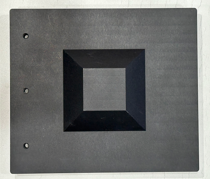
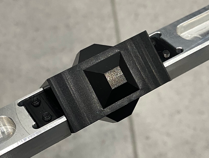
When deploying two or more laser profilers together, calibration targets must be used for calibration. The size and dimensions of calibration targets are determined by the model, number, and location of laser profilers. The figure below shows a common calibration target.
|

|

|
|
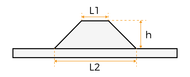
The calibration target consists of a foundation and a right square frustum ("frustum" for short) on top of the foundation.
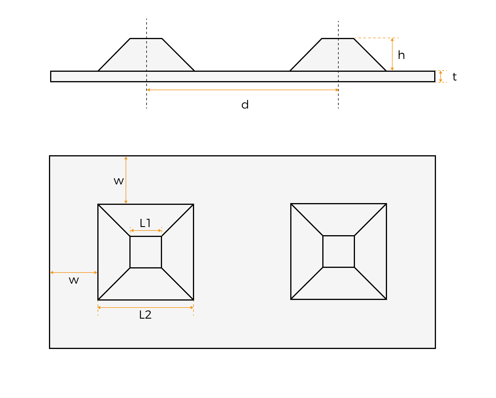
As shown in the figure below, the dimensions of the frustum include the upper base length (L1), lower base length (L2), and height (h), which are determined by the model of the laser profiler. The foundation dimensions include the translation distance (d), margin width (w), foundation thickness (t), etc., which are determined by the positional relationship between the laser profilers.
Principles for Calibration Target Design
To ensure calibration accuracy, the laser profiler and the calibration target should meet the following positional relationship:
-
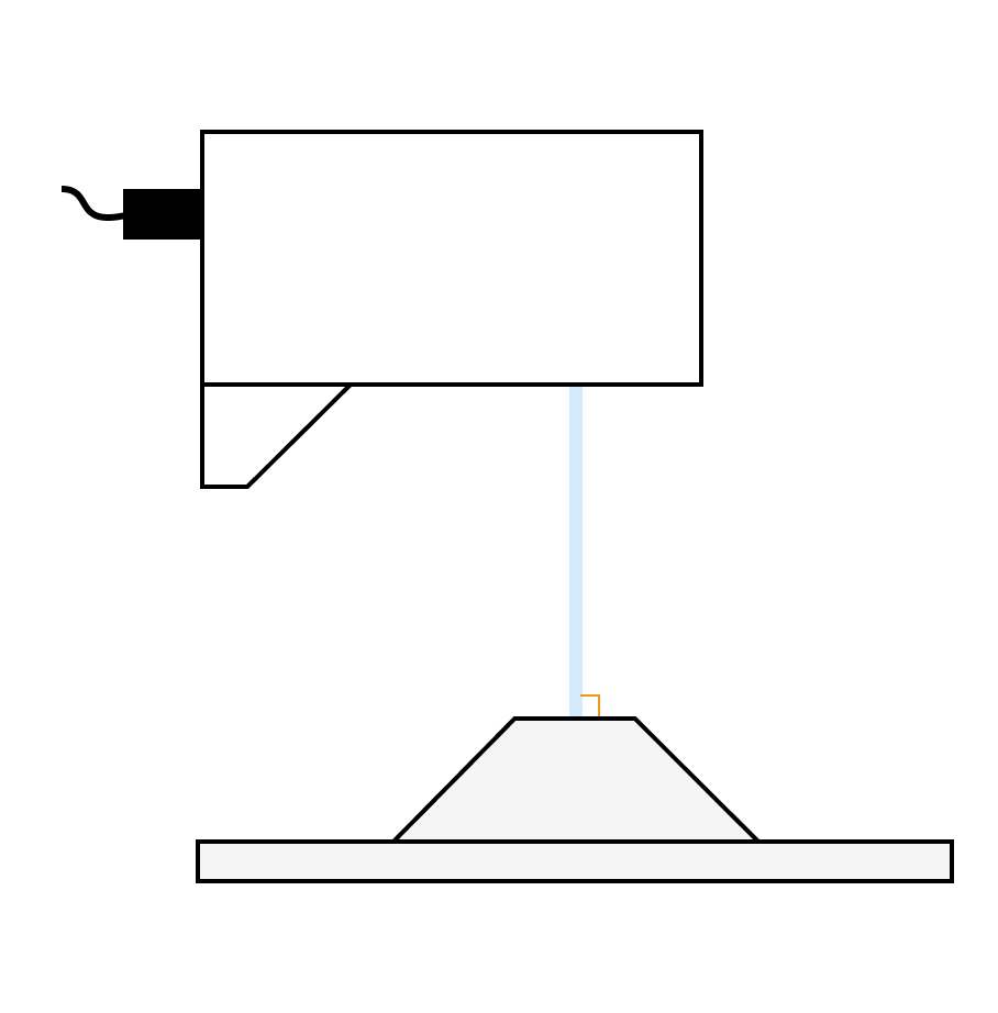
The laser projected by the laser profiler should be perpendicular to the surface of the frustum.
-
The foundation surface of the calibration target should be positioned at the laser profiler’s reference distance (RD as shown in the figure) to achieve higher calibration accuracy.
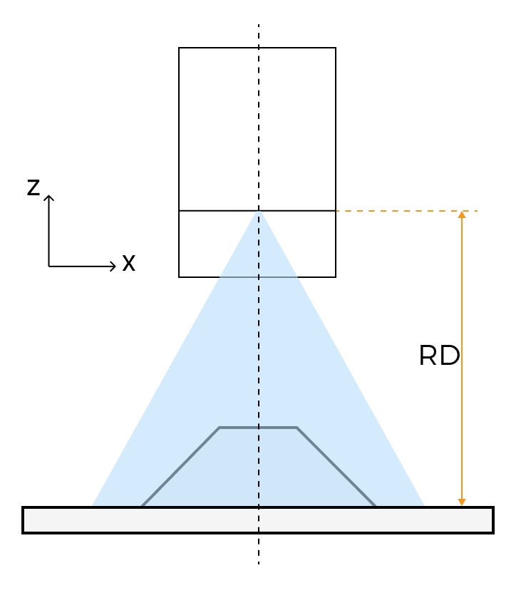
If site conditions are restricted, the calibration target can be slightly moved towards the direction closer to the laser profiler. -
Each field of view of the laser profiler includes the six feature planes of the calibration target (numbered 1 to 6 in the figure below) and exclude any other surfaces. The six feature planes refer to the upper base of the frustum, the foundation face, and the lateral faces of the frustum.

If unwanted surfaces appear in the acquired data, proceed to the following processing methods:
-
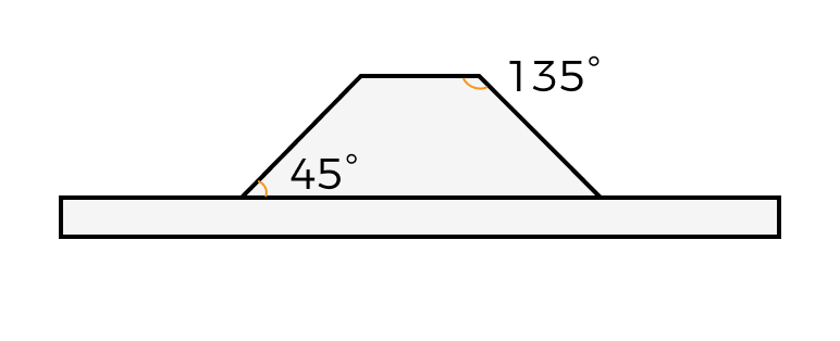
The lateral faces of the frustum form angles of 135° and 45° with the upper and lower bases, respectively, to facilitate the identification of feature planes.
Design of Calibration Target
The calibration target includes the frustum and the foundation. This section introduces how to calculate the dimensions of the frustum and the foundation.
Calculate the Frustum Dimensions
The dimensions of the frustum include the upper base length (L1), lower base length (L2), and height (h).
To meet the design principles, determine the frustum dimensions following these steps:
-
Lower base length (L2)
-
Check the measurement range of the laser profiler used for calibration.
-
Multiply 70% of the X-axis measurement range value at the reference distance and round down to the nearest integer. The calculated value will be the lower base length.
-
-
Upper base length (L1)
-
Calculate one-third of the lower base length (denoted as value a) and one-half of the lower base length (denoted as value b).
-
Calculate the average of a and b, then round down to obtain the upper base length.
-
-
Frustum height (h)
The height = 1/2 × (lower base length - upper base length)
The recommended frustum dimensions for different models of the laser profiler are shown in the table below:
| Model | Upper base length (mm) | Lower base length (mm) | Height (mm) |
|---|---|---|---|
LNX-8030-GL, LNX-7530-GL |
10 |
24 |
7 |
LNX-8080-GL, LNX-7580-GL |
30 |
60 |
15 |
LNX-75150-GL |
50 |
100 |
25 |
LNX-8300-GL, LNX-75300-GL |
106 |
212 |
53 |
Calculate the Foundation Dimensions
The shape of the foundation depends on the relative position between the laser profilers. This section introduces the foundation dimensions that need to be determined in Side-by-side, Reverse, and Opposite and Other Angled Layout Scenarios.
Side-by-side, Reverse, and Opposite
The typical scenarios for using multiple laser profilers and the required foundation dimensions are shown in the table below:
| Scenario | Side-by-side | Reverse | Opposite | |
|---|---|---|---|---|
Description |
The laser profilers are placed side by side along the X-axis to expand the X-axis measurement range. |
Two laser profilers are placed facing each other along the Y-axis to acquire complete data of the upper surface of the target object and eliminate visual blind spots. |
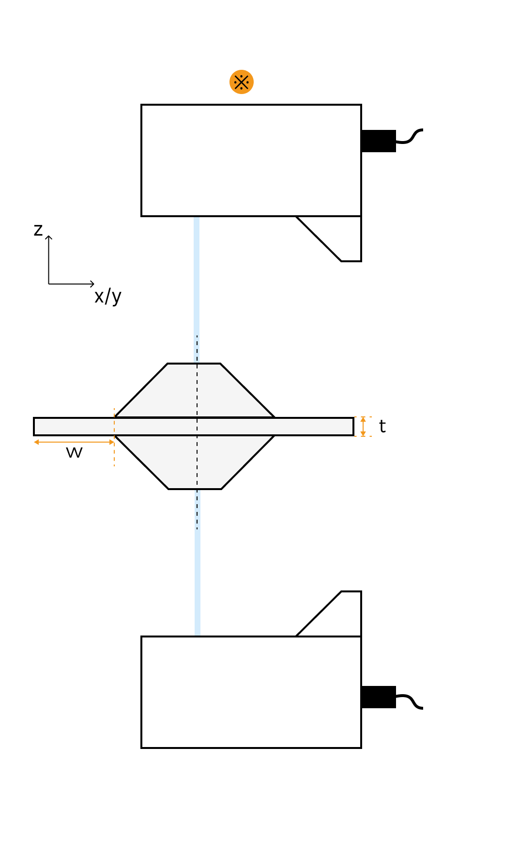
Two laser profilers are placed on the upper and lower surfaces of the target object to simultaneously acquire data from both surfaces and eliminate visual blind spots. |
|
Note |
A maximum of four laser profilers can be used in this scenario. |
When two laser profilers are positioned close to each other, they can share a single frustum. |
This scenario can be regarded as a special angled layout. |
|
Illustrative diagram |
|

|

|
|
Foundation dimensions |
Translation distance (d)
|
Margin width (w)
|
||
The description and calculation method of the foundation dimensions are as follows.
-
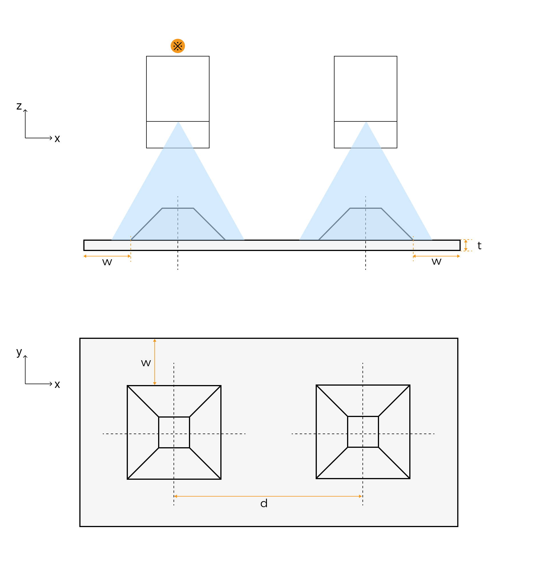
Translation distance (d): The distance between the centerlines of two adjacent frustums in the above diagram.
Determine the positions of the laser profilers based on measurement requirements to ensure their fields of view cover the target surfaces. The distance between the two laser profilers is the translation distance.
-
Margin width (w): The distance between the margin of the lower base of the frustum and the margin of the foundation of the calibration target.
It is recommended that the margin width be no less than half of the lower base length (L2) of the frustum.
-
Foundation thickness (t): It should be no less than 2 mm.
Other Angled Layout Scenarios
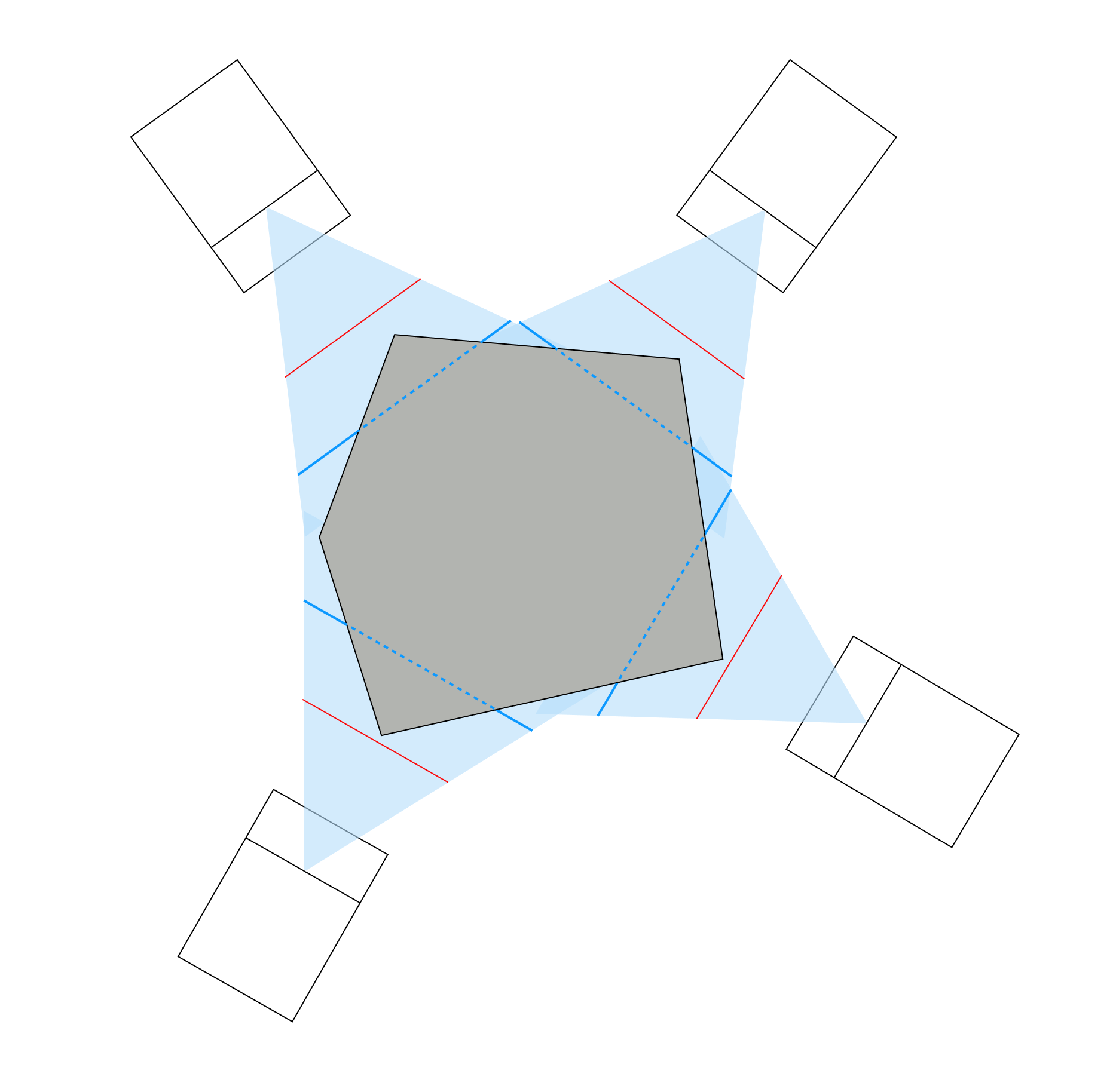
The laser profilers can be arranged at any angle to acquire high-quality surface data of the target object. In an angled layout scenario, the design of the calibration target is more complex and requires the use of drawing tools such as CAD. This section uses a scenario where four laser profilers are arranged with approximately 90° angles between adjacent profilers to illustrate how to calculate the foundation dimensions.
Follow these steps to calculate the foundation dimensions:
-
Place the laser profilers around the target object, ensuring that the X-axis measurement range covers the surface to be measured, while positioning the target object as close as possible to the laser profilers.
-
Red line: The X-axis measurement range on the near side
-
Blue line: The X-axis measurement range at the reference distance
-
-
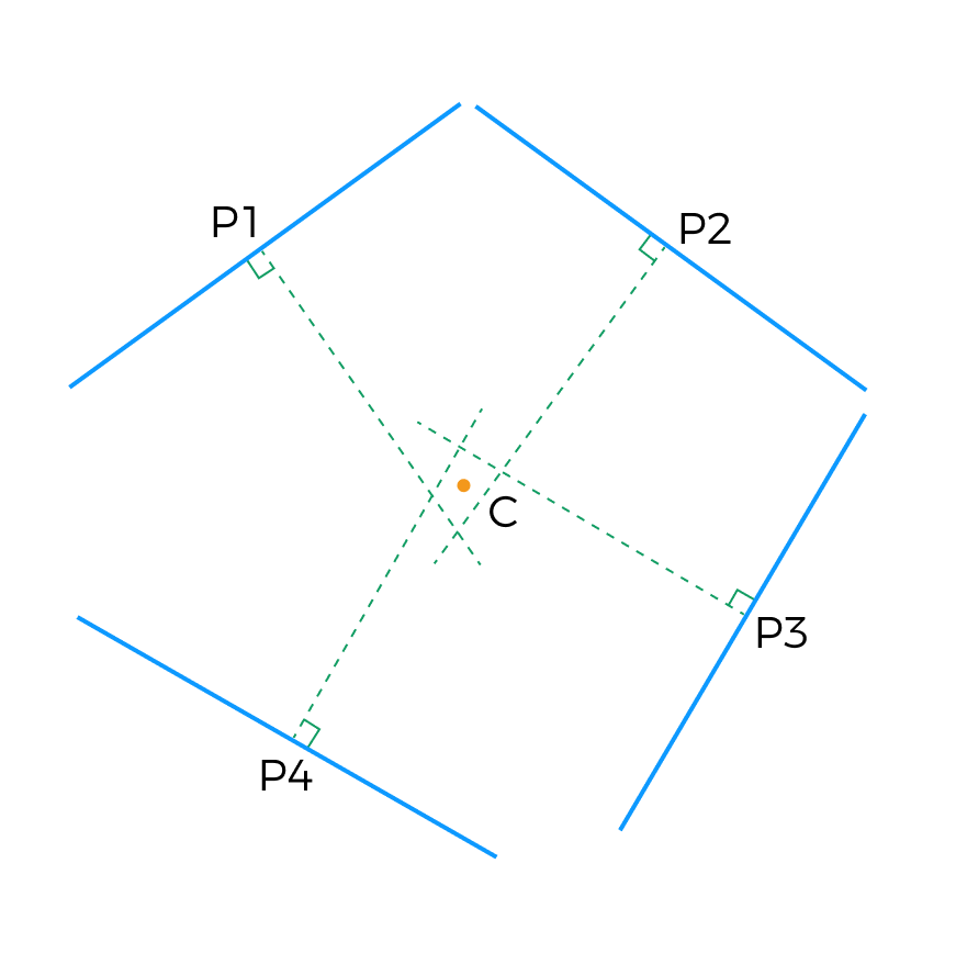
Draw line segments with a length equal to the X-axis measurement range at the reference distance (blue lines in the figure below). Mark the midpoints of the line segments as P1, P2, P3, and P4, and draw perpendicular bisectors (green lines in the figure below). The four perpendicular bisectors intersect, forming a quadrilateral. Designate the geometric center of the quadrilateral as point C.
-
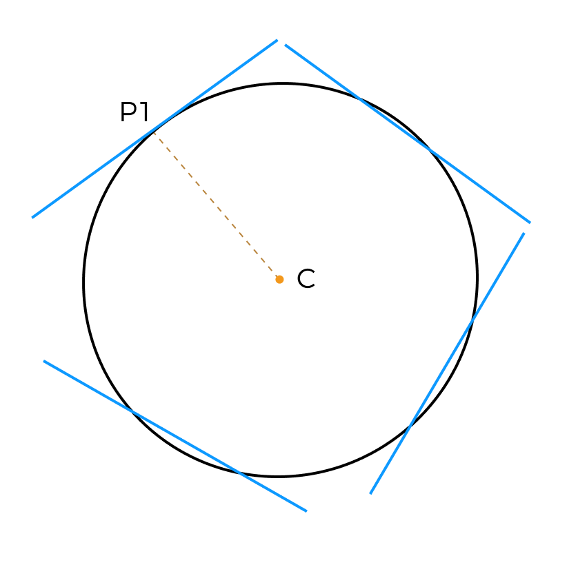
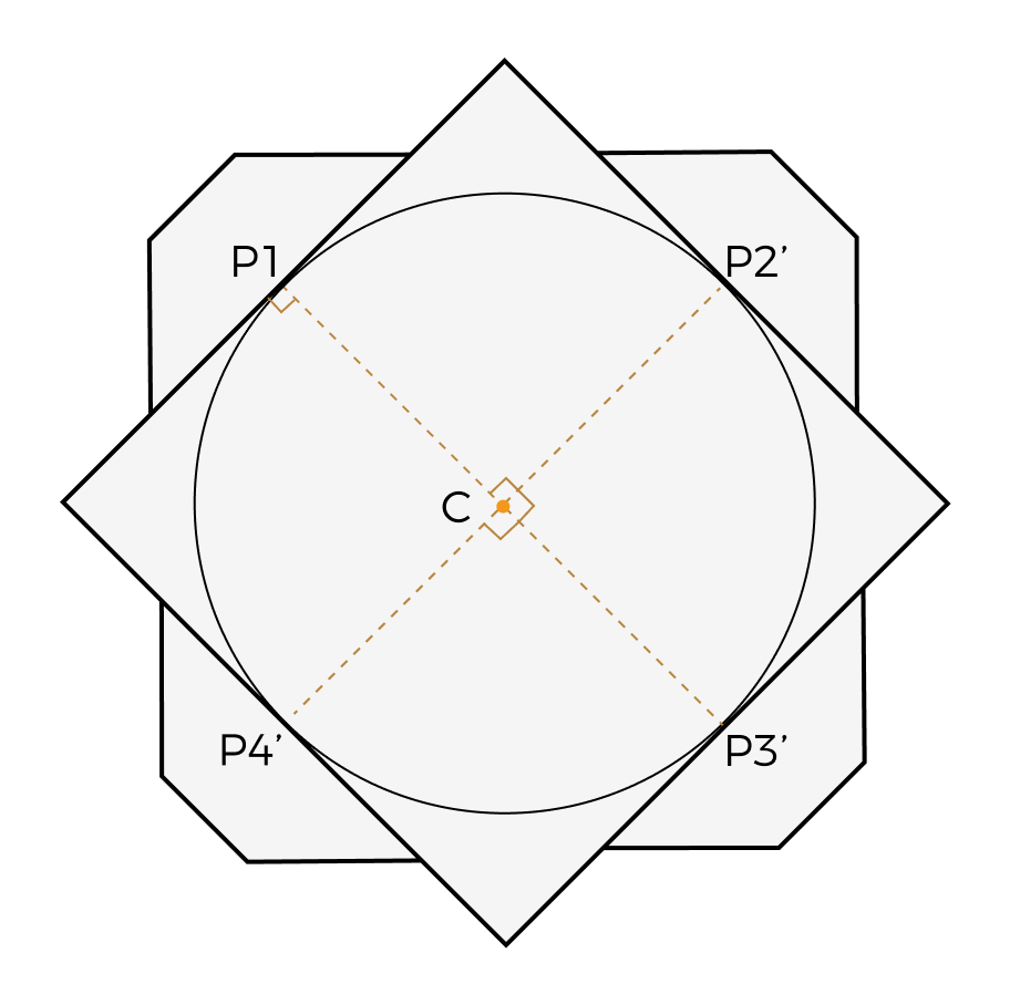
Draw a circle with the longest of the line segments CP1, CP2, CP3, and CP4 as the radius. This circle will be the incircle of the calibration target’s foundation. In the example, the longest line segment is CP1.
-
Rotate the line segment CP1 clockwise around point C by 90°, 180°, and 270° to obtain CP2', CP3', and CP4', respectively. Draw the tangents to circle C at points P1, P2', P3', and P4'. The square formed by these four tangents will be the circumscribed square of circle C. This square is the foundation of the calibration target.
-
According to the calculated frustum dimensions, draw the frustum on the foundation and align the center of the lower base of the frustum with the center of each side of the base (P1, P2', P3', P4').
-
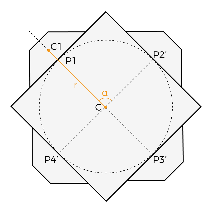
If you use Mech-MSR for calibration, obtain the following values for reference:
-
Rotation radius (r): The distance between the center point of the frustum (C1, the midpoint of the line connecting the upper and lower base centers of the frustum) and the center of the incircle on the foundation (C).
Rotation radius = 1/2 × frustum height (h) + radius of the incircle on the foundation (CP1)
-
Rotation angle (α): The included angle between the center lines of two adjacent frustums.
When the frustum shape is complex, use drawing tools to measure the rotation radius and rotation angle values.
-
Process and Accuracy Requirements
To ensure calibration accuracy, the following requirements should be met when manufacturing the calibration target:
-
Perform black anodizing and 120-grit sandblasting on the surface of the calibration target.
-
Based on actual requirements, process mounting holes at appropriate locations on the calibration target.
-
Do not apply chamfering to the margins and corners of the frustum.
To ensure calibration accuracy, the recommended calibration target accuracy for each model of the laser profiler is shown in the table below:
| Model | Linear dimension machining tolerance (mm) | Calibration target surface flatness tolerance (mm) |
|---|---|---|
LNX-8030-GL |
0.005 |
0.005 |
LNX-8080-GL |
0.02 |
0.02 |
LNX-8300-GL |
0.25 |
0.2 |
LNX-7530-GL |
0.005 |
0.005 |
LNX-7580-GL |
0.02 |
0.02 |
LNX-75150-GL |
0.1 |
0.05 |
LNX-75300-GL |
0.25 |
0.2 |