Configure Measurement Settings and Tolerances for the Feature
You need to configure the measurement settings and tolerances for the feature. This article describes how to configure the measurement settings and tolerances for Circle01. You can configure parameters as needed based on this document.
|
Tolerance refers to the difference between the maximum and minimum allowable dimensions based on the nominal value. For example, when manufacturing a cylinder with a length of 50 mm, if it is specified that an error within ±0.1 mm is acceptable, it can be said that "the tolerance is ±0.1 mm". |
Configure Measurement Settings for the Feature
Follow the steps below:
-
Right-click Circle01 in the Features section of the resource tree on the left side of the Configuration interface, then select Measurement Settings.
-
In the pop-up dialog box, In-control and Report under each tab are enabled by default. It is recommended that you keep the default settings.
-
When In-control is enabled, the measurement data of the feature will be used for subsequent OK and NG judgments and displayed in various sections of the software interface. When In-control is disabled, the feature’s measurement data will only be stored in the historical data. You can view the measurement data of the feature in the historical data using the filter feature.
-
When Report is enabled, the measurement data of the feature will be displayed in the exported report. The Report feature is enabled by default.
-
-
Enter relevant information in the Comment field as needed. For example, if the current feature does not need to be included in the measurement, you can note the reason in the Comment field under the General tab of this dialog box, to serve as a reference for future measurements and analysis.
Configure Tolerances for the Feature
Follow the steps below:
-
Right-click Circle01 in the Features section of the resource tree on the left side of the Configuration interface, then select Measurement Settings.
-
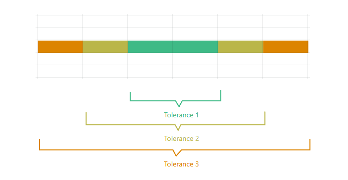
In the pop-up dialog box, click the X tab. Based on the part specifications, set Tolerance in effect, Tolerance 1, Tolerance 2, and Tolerance 3. For example, you can set Tolerance 1 to -1mm to 1mm, Tolerance 2 to -2mm to 2mm, and the Tolerance 3 to -3mm to 3mm, then set Tolerance 1 as the effective tolerance. This example is for reference only. You can set tolerance parameters according to the actual situation.
The following image is an example of a set tolerance 1, 2, and 3, provided to assist with understanding. The green one represents tolerance 1, the yellow one represents tolerance 2, and the orange one represents tolerance 3.
-
Choose whether to apply the tolerance settings to all measurement items of the current part. If you want to apply it, click Apply, then click Save.
If you choose to apply the tolerance settings to all measurement items of the current part, all tolerance settings here will be applied to all measurement items of the current part. At this point, the tolerance settings for the X sub-item will be used for other sub-items of the current feature, as well as for items including features, geometric measurements, and GD&T measurements created later. You will not need to set tolerance parameters for other sub-items of the current feature, nor for items including features, geometric measurements, and GD&T measurements created later.
-
Measurement items refer to the elements that you can create in the current project, which require measurement to obtain measured values, including features, geometric measurements, and GD&T measurements.
-
Measurement items can also refer to sub-items of each measurement item. For example, the sub-items for a circle measurement item include X, Y, Z, and radius.
-