Terms and Concepts
To ensure you can understand the technical terms and professional expressions, this document compiles concept explanations scattered throughout the manual for easy reference.
Terms and Concepts
Measurement Project Configuration
- IPC
-
An industrial PC (IPC) is a computer intended for industrial purposes. Compared with regular computers, IPCs have higher reliability and precision standards.
- ROI
-
Region of Interest (ROI) refers to a specific region that is selected for analysis or processing during image processing.
- Sentinel LDK
-
Sentinel License Development Kit (LDK) is a comprehensive software development toolkit that helps you efficiently manage software licenses and usage rights.
- C2V file
-
A Customer to Vendor (C2V) file is used to generate the V2C or V2CP file. This file contains information about the software licensing device.
- V2C file
-
A Vendor to Customer (V2C) file is used to update the license offline. This file contains information about the license provided to you.
- V2CP file
-
A Vendor to Customer Package (V2CP) file is a package file that contains multiple V2C files.
- Mech-Metrics project
-
A Mech-Metrics project is created in Mech-Metrics to manage and maintain an inline measurement project. With a complete set of functional configurations, the Mech-Metrics project provides end-to-end measurement process management from part import, reference frame establishment, and measurement item configuration to data collection and analysis.
- Mech-Metrics measurement project
-
A Mech-Metrics measurement project is the same as a Mech-Metrics project. The two words can be used interchangeably.
- Mech-Vision solution
-
Created in Mech-Vision, a Mech-Vision solution is a collection of functional configurations and data for robot, communication, vision processing, and path planning required for a vision application.
- Mech-Vision measurement solution
-
A Mech-Vision measurement solution refers to a Mech-Vision solution specifically configured for measuring a particular part. When you use Mech-Metrics, you need to associate a part with its Mech-Vision measurement solution.
- Mech-Vision project
-
A Mech-Vision project refers to a 3D vision project created in Mech-Vision to achieve a specific vision task. One or more Mech-Vision projects make up a Mech-Vision solution. Projects cannot be used independently and must be part of a solution.
- Mech-Vision measurement project
-
A Mech-Vision measurement project is a specialized Mech-Vision project dedicated to measuring a specific feature of a part. When you use Mech-Metrics, you need to associate the feature with its Mech-Vision measurement project.
The correspondence between Mech-Metrics resources and Mech-Vision resources is summarized as follows:
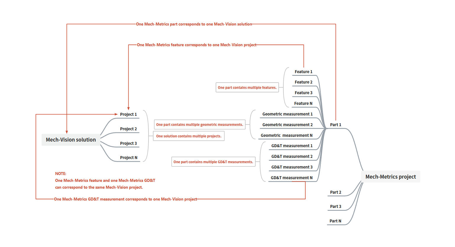
- Part
-
A part refers to an individual workpiece that is processed or assembled during production.
A Computer-Aided Design (CAD) model of a part refers to a digital 3D model created using CAD software to represent the shape, dimensions, and other characteristics of a part. The imported CAD model of the part represents all such parts.
- Feature
-
A feature refers to specific geometric elements or attributes of a part, such as its shape, dimensions, and so on.
The feature types supported by this software are: circles, slots, cylinders, points, lines, and planes.
- Feature attribute
-
The software supports three types of feature attributes for measurement:
-
Point, also referred to as the center or origin.
-
Line, also referred to as the orientation or normal.
-
Surface, also referred to as the plane.
-
- Feature ID
-
The ID is the unique identifier of the feature in the current part. The ID is an integer between 1 and 999.
Each feature must be associated with a Mech-Vision project, which is used to measure the feature. The project ID is the unique identifier of the project in the Mech-Vision solution.
In Mech-Metrics, feature IDs correspond to the measurement positions on the part, while Mech-Vision project IDs represent the sequence of projects in the Mech-Vision solution. The two types of IDs are not directly related, and multiple measurement positions can be associated with the same Mech-Vision project.
- Feature picking
-
Feature picking refers to manually selecting several points of a feature in the central 3D view using the mouse. This is done to determine the position and dimensions of the feature in the view and to pick the nominal values of the feature.
- Nominal value
-
Nominal values refers to the ideal or target dimensions of a feature, which are the standard values that the designer expects the part to achieve during the manufacturing process. The nominal values serve as a reference to determine the shape, size, and other requirements of the part.
- Tolerance
-
Tolerance refers to the difference between the maximum and minimum allowable dimensions based on the nominal value. For example, when manufacturing a cylinder with a length of 50 mm, if it is specified that an error within ±0.1 mm is acceptable, it can be said that "the tolerance is ±0.1 mm".
- Measurement item
-
Measurement items refer to the elements that you can create in the current project, which require measurement to obtain measured values, including features, geometric measurements, and GD&T measurements.
Measurement items can also refer to sub-items of each measurement item. For example, the sub-items for a circle measurement item include X, Y, Z, and radius.
- Annotation
-
An annotation displays data such as nominal values, measured values, and deviations for each sub-item of the measurement item (e.g., X, Y, and Z for a circle measurement item) in a table.
- Robot reference frame
-
A robot reference frame refers to the reference frame used by the robot to describe positions and orientations. The origin of the robot reference frame is located at the robot base and remains fixed.
- Part reference frame
-
A part reference frame is a reference frame established based on certain standards that a specific part of the vehicle body must follow during its processing and manufacturing.
- Vehicle reference frame
-
A vehicle reference frame is a reference frame established at the early stages of vehicle design to define the position and orientation of various parts of the vehicle.
- Part-based establishment
-
Part-based establishment refers to establishing a reference frame using the reference features of a part. This reference frame is determined by the features of the part itself. Establishing the reference frame on the part can relax the clamping precision requirements. Since the reference features of each part may differ, the resulting part reference frame will also vary for each part.
- Fixture-based establishment
-
Fixture-based establishment involves establishing the reference frame on the fixture. Since the fixture is fixed, only one frame establishment is needed to convert all parts to the fixture reference frame. This method requires high clamping precision.
- RPS alignment
-
RPS alignment, which stands for Reference Point System Alignment, uses a set of features to constrain the translation and rotation of the part, aligning the part with its CAD model.
- Best fit alignment
-
Best Fit alignment uses at least three features for a best fit alignment, ensuring that the part is aligned with its CAD model.
- GD&T
-
In this software, geometric dimensioning and tolerancing (GD&T) measurements are a type of measurement items developed based on GD&T. GD&T is an international standard used to define the geometric characteristics of a part. It provides a unified set of symbols and language to specify requirements related to the shape, size, location, and orientation of the part.
- Position
-
Position is used to describe the deviation of features such as points, lines, and planes from their ideal positions.
- Flatness
-
Flatness is used to describe the deviation of a surface from its ideal plane.
- Geometric measurement
-
In this software, geometric measurements include distance and angle measurements.
- Distance
-
Distance measurement is used to measure the distance between two features. Specifically, distance measurement can be used to measure point-to-point, point-to-line, point-to-plane, line-to-line, line-to-plane, and plane-to-plane distances between two features. For example, you can select two circle features and choose the center for these two circles to measure the distance between their centers.
- Angle
-
Angle measurement is used to measure the angle between two features. Specifically, angle measurements can be used to measure the line-to-line, line-to-plane, and plane-to-plane angles between two features. For example, you can select two circle features and choose the orientation for these two circles to measure the angle between their normals.
Measurement Project Deployment
- Repeatability testing
-
Repeatability testing refers to performing multiple measurements of the same measurement target or object under the same conditions, to assess the consistency of the measurement results.
- Static repeatability testing
-
In static repeatability testing, the part is fixed in place using a fixture. The robot, equipped with a camera, moves to the measurement position of the part’s feature. At this position, the robot remains still while the camera captures multiple images of the feature. For example, if a part has 5 features, the static repeatability testing is performed as follows:
-
Secure the part: Secure the part using a fixture.
-
Move the robot: Move the robot to the position of Feature 1 on the part.
-
Capture images: The camera captures 20 images of Feature 1 until the test for this feature is complete.
-
Repeat the process: Repeat steps 2-3 for the remaining 4 features. The static repeatability test for the current part is then complete.
-
- Semi-dynamic repeatability testing
-
In semi-dynamic repeatability testing, the part is fixed in place using a fixture, and the robot, equipped with a camera, moves sequentially to the measurement positions of each feature on the part and takes photos. After completing one round of photo captures, the same operation is repeated to complete the remaining rounds. For example, if a part has 5 features, the semi-dynamic repeatability testing is performed as follows:
-
Secure the part: Secure the part using a fixture.
-
First round of photo capture: The robot, equipped with the camera, takes photos of all the features on the part in sequence (Feature 1 → Feature 2 → Feature 3 → Feature 4 → Feature 5).
-
Repeat the process: The robot repeats step 2 for the remaining 19 rounds of photo captures. The semi-dynamic repeatability test for the current part is then complete.
-
- Dynamic repeatability testing
-
In dynamic repeatability testing, the process is similar to semi-dynamic repeatability testing, except that the part is re-clamped at the beginning of each measurement round. After the part is clamped and secured, the robot, equipped with a camera, moves sequentially to the measurement positions of each feature on the part and takes photos. For example, if a part has 5 features, the dynamic repeatability test is performed as follows:
-
Secure the part: Secure the part using a fixture.
-
First round of photo capture: The robot, equipped with the camera, takes photos of all the features on the part in sequence (Feature 1 → Feature 2 → Feature 3 → Feature 4 → Feature 5).
-
Re-clamp the part: Re-clamp the part.
-
Repeat the process: Repeat steps 2-3 for the remaining 19 rounds of photo captures. The dynamic repeatability test for the current part is then complete. The semi-dynamic repeatability test for the current part is then complete.
-
- Accuracy
-
Accuracy refers to the closeness or error size between the measurement results and the true value.
- Range
-
Range is a statistical indicator that measures the difference between the maximum and minimum values in a data set. It is used to represent the dispersion of the data.
- 3D
-
The 3D tab on the repeatability test results page shows the change trend of the 3D coordinates of the feature points with the number of measurements.
-
A feature point refers to the point at the location of the feature. For example, the feature point of a circle feature is the center of the circle.
-
3D coordinates refer to the position of a point in a 3D coordinate system.
-
On the 3D tab, 3D represents the 3D distance between the feature point position measured each time and the feature point position measured the first time.
-
- PLC
-
A Programmable Logic Controller, abbreviated as PLC, is a programmable computing device used to manage electromechanical processes, typically applied in industrial fields.
- Host computer
-
A host computer refers to a computer used in industrial control systems to monitor, manage, and control lower-level devices (such as PLCs, robots, etc.).
- Robot side
-
A robot is a programmable multi-purpose handling device with some autonomy that can perform tasks such as movement, manipulation, or positioning. In the Mech-Mind Vision System, it performs intelligent tasks based on the results output by the vision system.
A robot cell usually consists of a robot body, a controller, and a teach pendant.
In industrial applications that require a high level of automation, a PLC can be used to control the motion and operation of the robot. If a higher level of control and monitoring is required, a host computer can also be used to perform more complex programming and control of the robot, such as path planning, task planning, and motion control. The Mech-Mind Vision System can be used together with the PLC and host computer.
In this document, “robot side” is used as a generic term for the robot, PLC, or host computer.
- CMM
-
A Coordinate Measuring Machine (CMM) is a typical coordinate measuring device. Using a measurement platform as a reference, it establishes a mechanical reference frame, collects the coordinates of measurement points on the surface of a part, and projects them into a spatial reference frame to construct a 3D model of the part.
- Correlation
-
Correlation refers to the degree of consistency between the measurement results of two different measurement devices when measuring the same dimension of the same part.
- Error compensation
-
Error compensation is a technique or method used to correct measurement or operational errors caused by uncertainties, inaccuracies, or deviations by adjusting or calibrating the output of a system or device. The purpose of error compensation is to improve the accuracy of the system or device, ensuring its output is closer to the true or target value.
- Correlation analysis and compensation
-
Correlation analysis and compensation refer to analyzing the relationship between the measurement results of two different measuring devices, followed by compensating the results of one device to improve the reliability of the device.
- Measurement record
-
Measurement records refer to the measurement data stored in the historical data of the software.
- MSA
-
Measurement Systems Analysis, short for MSA, is a set of experiments and analyses used to evaluate the capability, performance, and measurement uncertainty of a measurement system. The MSA report is a report provided by Mech-Metrics to evaluate the reliability of the inline measurement system.
- Communication
-
During the communication between the robot and Mech-Metrics, the robot establishes a connection with Mech-Vision, and Mech-Vision establishes a connection with Mech-Metrics. Once these connections are established, the specific communication steps are as follows:
-
The robot runs the measurement program, which triggers Mech-Metrics to run.
-
Mech-Metrics uses Mech-Vision for measurement.
-
Mech-Vision returns the measurement data to Mech-Metrics.
-
Mech-Metrics sends the measurement result (OK or NG) back to the robot.
-
Measurement Data Analysis
- SPC
-
SPC stands for Statistical Process Control, which refers to the use of statistical methods to monitor each stage of the production process in order to ensure and improve product quality.
- USL
-
The Upper Specification Limit, abbreviated as USL, is the upper limit of a dimension, which is the nominal value plus the upper tolerance. For example, if the nominal length of a feature is 5mm and the tolerance is -1 to 1mm, the USL would be 6mm.
- LSL
-
The Lower Specification Limit, abbreviated as LSL, is the lower limit of a dimension, which is the nominal value plus the lower tolerance. For example, if the nominal length of a feature is 5mm and the tolerance is -1 to 1mm, the LSL would be 4mm.
- 3σ rule
-
σ represents the standard deviation. The 3σ rule, also known as the three-sigma rule, is a method used in statistics to exclude outliers. It assumes that the data follows a normal distribution, and any data point that exceeds the mean plus or minus three standard deviations is considered an outlier and should be removed from the dataset. The 3σ control limits are used to check whether data points lie within three standard deviations of the mean.
- CL
-
The Central Line, abbreviated as CL, is a line consisting of the average values (
 ).
). - UCL
-
The Upper Control Limit, abbreviated as UCL, is the value obtained by adding 3σ to the average value.
- LCL
-
The Lower Control Limit, abbreviated as LCL, is the value obtained by subtracting 3σ from the average value.
- Control chart
-
A control chart, is used to analyze and determine whether a process is in a state of control. It includes control limits. The control chart is based on the 3σ rule in normal distribution, where the central line represents the average value (
), and the upper and lower control limits are calculated by adding and subtracting 3σ from the average value. These limits are used to identify if there are any issues occurring in the process.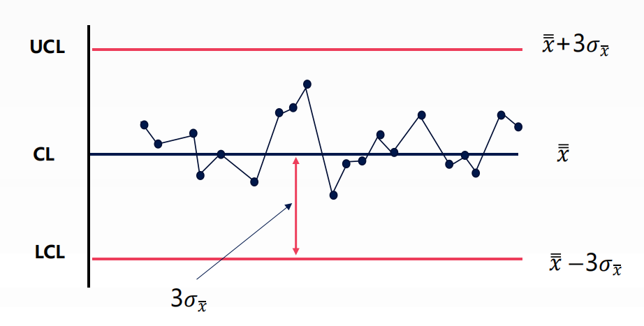
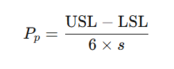
- Pp
-
The Process Performance, abbreviated as Pp, is used to assess whether the performance of a process meets specification requirements. The formula for calculating Pp is as follows, where s represents the sample standard deviation.
- Ppk
-
The Process Performance Index, abbreviated as Ppk, is used to assess whether the performance of a process meets specification requirements. Compared to Pp, Ppk takes into account the impact of the process performance mean. The formula for calculating Ppk is as follows, where
represents the sample mean and s represents the sample standard deviation.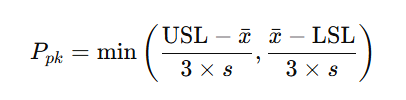
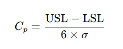
- Cp
-
The Process Capability Index, abbreviated as Cp, is used to assess whether the capability of a process meets specification requirements. The formula for calculating Cp is as follows, where σ represents the population standard deviation.
- Cpk
-
The Process Capability Index, abbreviated as Cpk, is used to evaluate whether the capability of a process meets specification requirements. Unlike Cp, Cpk takes into account the effect of the process mean. The formula for calculating Cpk is as follows, where
represents the population mean and σ represents the population standard deviation.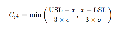
Abbreviations
This section summarizes the abbreviations used in the manual for reference. For detailed explanations of the abbreviations, see the Terms and Concepts section of this document.
- CAD
-
Computer-Aided Design
- CL
-
Central Line
- CMM
-
Coordinate Measuring Machine
- Cp
-
Process Capability
- Cpk
-
Process Capability Index
- C2V
-
Customer to Vendor
- GD&T
-
Geometric Dimensioning and Tolerancing
- IPC
-
Industrial PC
- LCL
-
Lower Control Limit
- LSL
-
Lower Specification Limit
- MSA
-
Measurement Systems Analysis
- PC
-
Personal Computer
- PLC
-
Programmable Logic Controller
- Pp
-
Process Performance
- ROI
-
Region of Interest
- Ppk
-
Process Performance Index
- RPS
-
Reference Point System
- SPC
-
Statistical Process Control
- UCL
-
Upper Control Limit
- USL
-
Upper Specification Limit
- V2C
-
Vendor to Customer
- V2CP
-
Vendor to Customer Package
- LDK
-
License Development Kit