Mech-Mind IPC STD User Manual
Preface
This user manual applies to the industrial PCs (IPCs) of the Mech-Mind IPC STD series.
The Mech-Mind IPC STD series supports the following models:
-
IPCW-i5-16G-512G-EU
-
IPCW-i5-16G-512G-US
-
IPCW-i5-16G-512G-UK
-
IPCW-i5-16G-512G-JP
-
IPCW-i5-16G-512G-KR
1. Safety Instructions
-
To ensure safe usage, please do not use the product until you have read this user manual and understand how to use the product correctly. Failure to follow the instructions for use and maintenance in this manual may result in damage to the IPC, personal injury, or any loss to third parties.
-
Following the warnings and precautions in this manual can effectively reduce risks, but it cannot eliminate all risks.
-
The content of this user manual has been reviewed, and each step has been carefully checked during the writing process. If you find any questions or errors, please feel free to contact Mech-Mind.
-
This product must be installed, connected, used, and maintained by qualified professionals. Please ensure proper transportation, storage, installation, connection, usage, and maintenance to guarantee the safe operation of the product.
General Safety Precautions
Follow the safety precautions outlined below:
-
Be sure to comply with the general safety guidelines for the location where this product is used.
-
When moving, installing, or maintaining this product, ensure that the power supply and power cables are disconnected.
-
Do not use voltage exceeding the rated voltage range, as it may result in incidents such as fire or electric shock.
-
If a large amount of dust, water, or other liquids enters the product, immediately disconnect the power supply, unplug the power cable, and contact Mech-Mind.
-
Do not drop this product onto hard surfaces.
-
Do not use this product in environments where the temperature exceeds the rated temperature.
2. Technical Specifications
| Product | Mech-Mind IPC STD |
|---|---|
Model |
|
Configuration |
|
CPU |
Intel® Core i5-12400 2.5 GHz |
Memory |
16 GB DDR4 |
GPU card |
No discrete graphics card |
Storage |
512 GB SSD |
Operating system |
Windows 10 IoT Enterprise LTSC |
Wireless network |
2 x External WiFi antennas |
Switches |
1 x POWER switch
|
IO interfaces |
|
Network ports |
4 x 2.5 GbE |
USB ports |
8 x USB 3.2 GEN2 |
Serial ports |
4 x RS232
|
Digital IO |
15-pin DIO |
Display interfaces |
HDMI/DP |
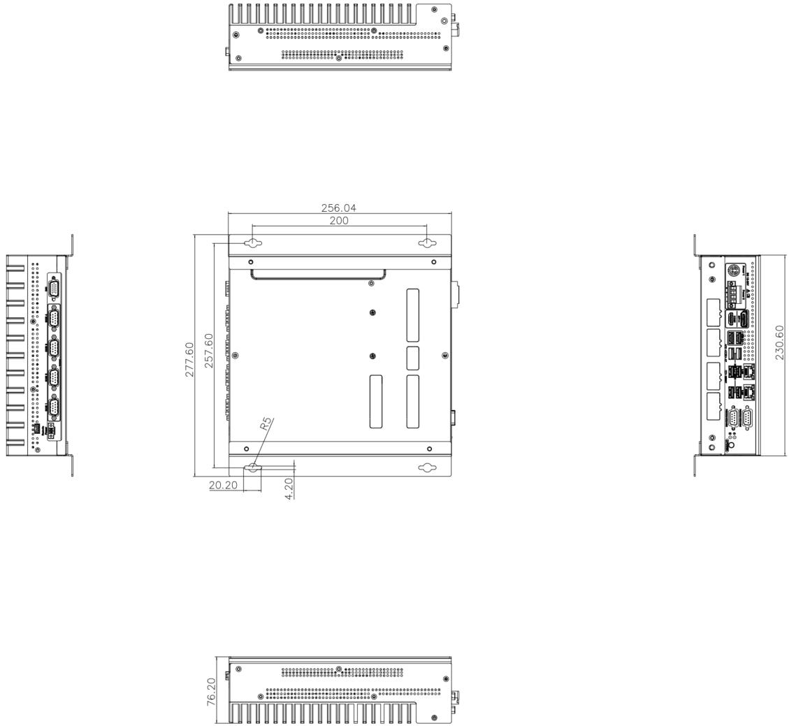
Mechanical features |
|
Dimensions (W x D x H) |
230 mm x 256 mm x 76 mm |
Weight (net) |
About 3 kg |
Electronics |
|
Power supply |
Adapter AC input: 100–240 V, 2.3 A, 50–60 Hz Adapter DC output: 19.0 V, 9.47 A, 180 W |
Rated power |
180 W |
Environmental |
|
Operating environment |
Operating temperature: -20°C to 45°C; humidity: 10% to 95%; non-condensing |
Storage environment |
Storage temperature: -40°C to 85°C; humidity: 10% to 95%; non-condensing |
Safety & Certification |
|
Certification |
CE/FCC/VCCI/KC/NRTL |
Warranty |
|
Warranty period |
One year |
|
For more information about certification, please contact Mech-Mind Technical Support. |
3. Product Overview
3.1. Overview
This product is a fanless system for harsh industrial environments, powered by a 12th-generation Intel Core processor, and has dual-260-pin DDR4 SDRAM SODIMM slots that support up to 64 GB memory (16 GB preloaded). This product provides IO interfaces including a digital I/O port, an HDMI port, a DP port, four 2.5 GbE ports, eight USB 3.2 GEN2 ports, two RS232/422/485, and four RS232 connectors.
3.2. Product Views
3.2.1. Front View
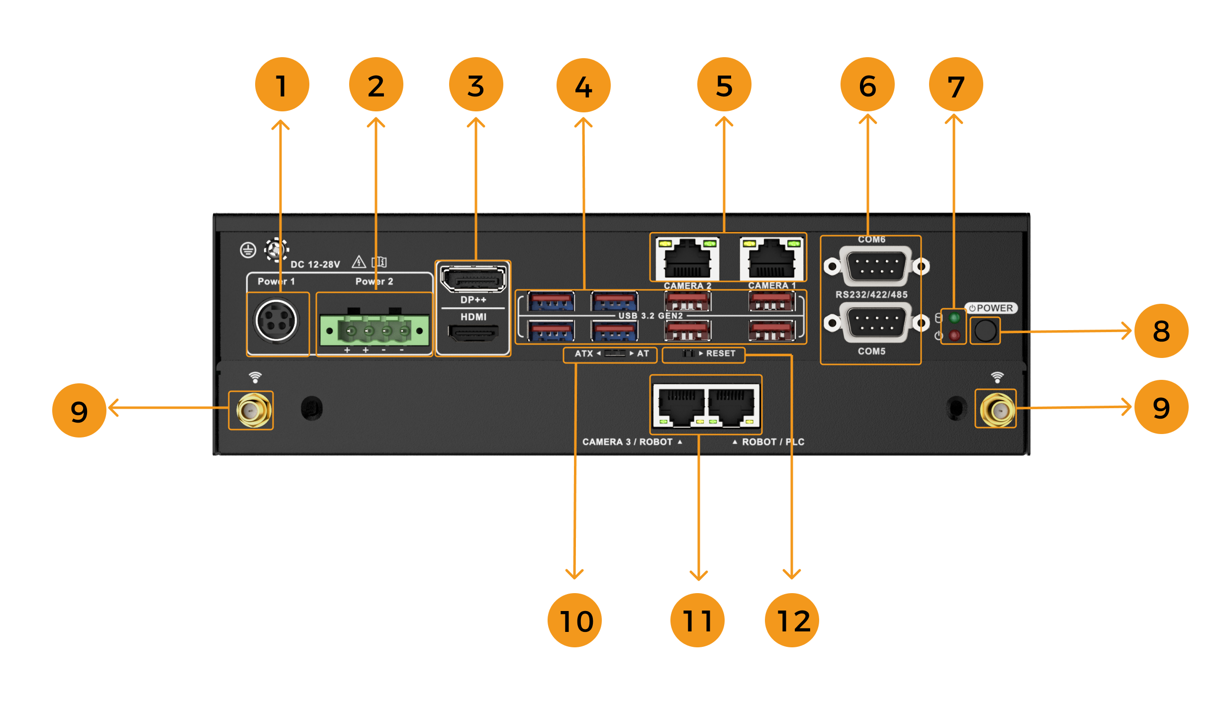
The following figure shows the front panel of this product and the interfaces on it.
| No. | Description | No. | Description |
|---|---|---|---|
1 |
DC Jack, DC 12–28V |
2 |
Power terminal block, DC 12V to 28V |
3 |
HDMI/DP port |
4 |
8 x USB 3.2 GEN2 ports |
5 |
2 x RJ45 2.5 GbE (CAMERA 1 and CAMERA 2) |
6 |
2 x DB9 serial ports (COM 5 and COM 6), supporting RS232/422/485 |
7 |
Hard drive/Power LEDs* |
8 |
POWER button (switch) |
9 |
2 x WiFi antennas |
10 |
Power mode switch, supporting AT/ATX |
11 |
2 x RJ45 2.5 GbE (CAMERA 3/ROBOT and ROBOT/PLC) |
12 |
RESET button (switch) |
| When the IPC is powered on, the hard drive LED should blink, indicating that the hard drive is performing read/write operations. |
4. Installation
4.1. Unpacking Checklist
| If some of the components listed in the checklist below are missing, please do not proceed with the installation and contact Mech-Mind Technical Support. |
This product is shipped with the following components:
| No. | Item | Quantity | Illustration |
|---|---|---|---|
1 |
Mech-Mind IPC STD |
1 |
|
2 |
Mounting bracket |
2 |
|
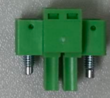
3 |
2-pin terminal |
1 |
|
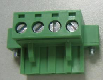
4 |
4-pin terminal |
1 |
|
5 |
Set screw |
8 |
|
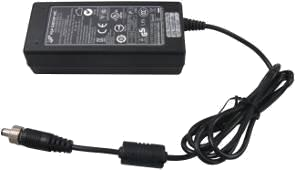
6 |
Power adapter |
1 |
|
7 |
Power cord |
1 |
Note that the power cords sold in different regions vary. |
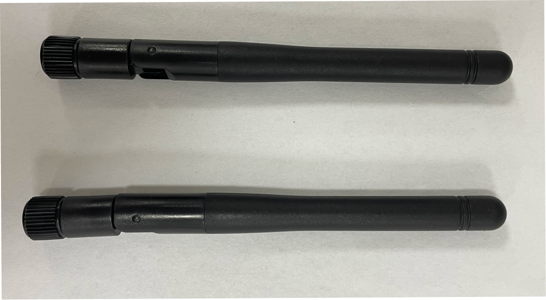
8 |
External WiFi antenna |
2 |
|


4.2. Installation Precautions
Before installing this product, please pay attention to the following installation precautions:
-
Read the user manual: The user manual for this product provides detailed instructions on installation and configuration options. Please read it before installation.
-
DANGER! Disconnect power: Ensure that the power to the IPC is completely disconnected during the installation process. Failure to do so may result in electric shock or personal injury.
-
Qualified personnel: This product must be installed by qualified professionals.
-
Air circulation: When installing this product, ensure there is adequate airflow. The cooling ventilation openings of this product must not be obstructed. Leave at least a 5 cm gap around the product to prevent overheating.
The above-mentioned cooling ventilation openings are not fan exhaust ports. This product does not come with a fan. -
Grounding: This product must be properly grounded.
4.3. Mount the IPC with Mounting Brackets
To mount the IPC onto a wall or some other surface using the two mounting brackets, please follow the steps below.
-
Turn the IPC over.
-
Align the retention screw holes in each bracket with the corresponding retention screw holes on the bottom surface.
-
Secure the brackets to the IPC by inserting retention screws into each bracket.
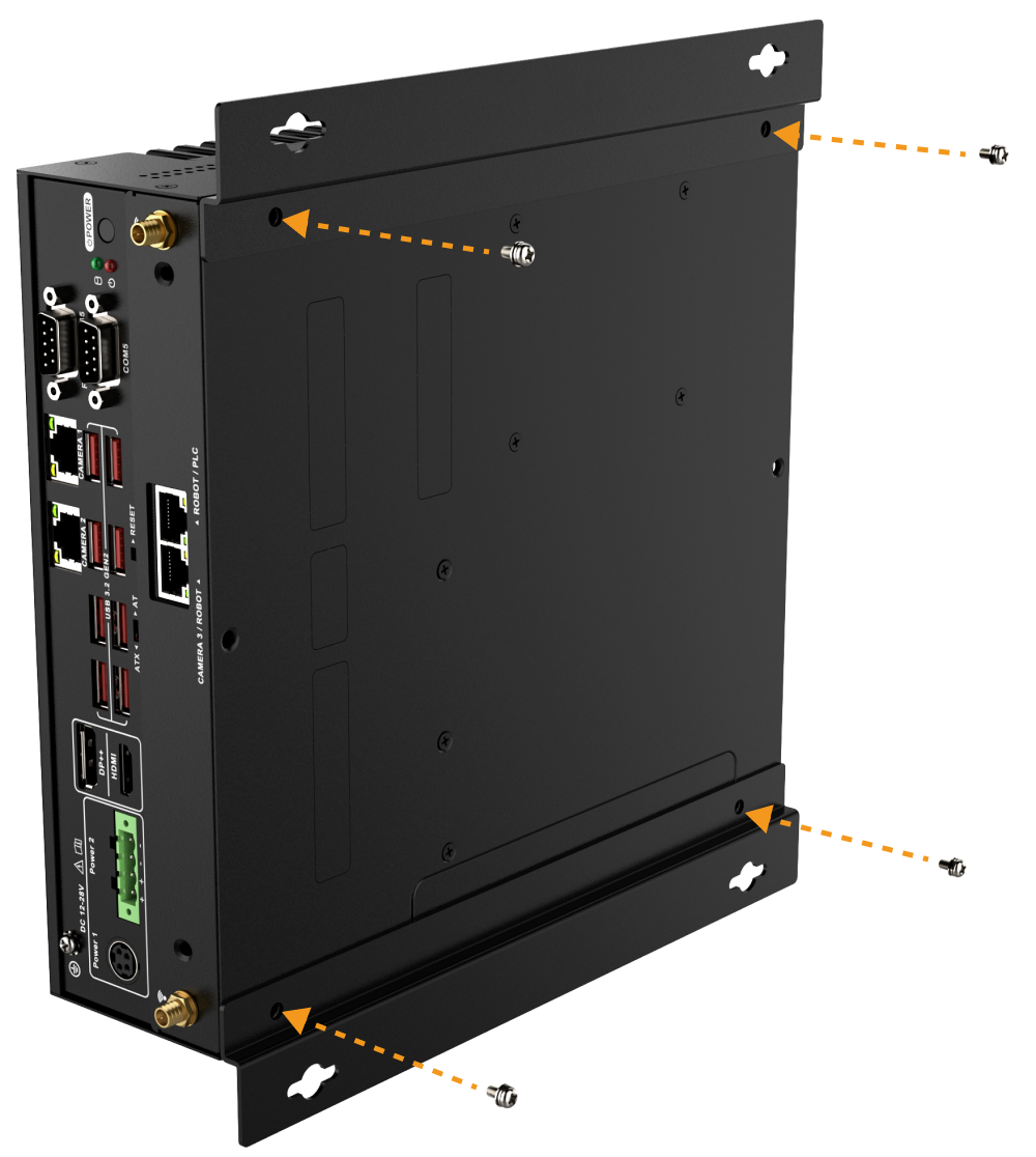
-
Drill holes into the intended mounting surface.
-
Align the mounting holes on both sides of the mounting bracket with the pre-drilled holes.
-
Use screws (prepared by yourself) to secure the IPC to the target mounting surface.
5. External Interface Description
5.1. AT/ATX Power Mode Selection
This product supports both AT and ATX power mode startup.
-
AT power mode: The IPC can automatically start up when the power supply is connected.
-
ATX power mode: The IPC can start up when you press the POWER button.
This setting can be switched via the AT/ATX power mode switch on the front panel, as shown in the image below.
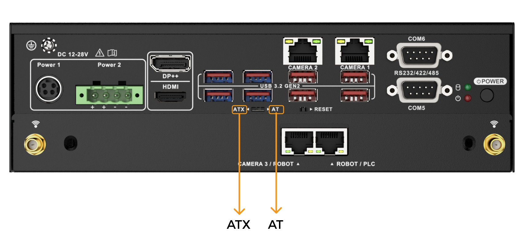
| The switch is located inside. Please use a precision tool such as a small screwdriver when switching the power mode. |
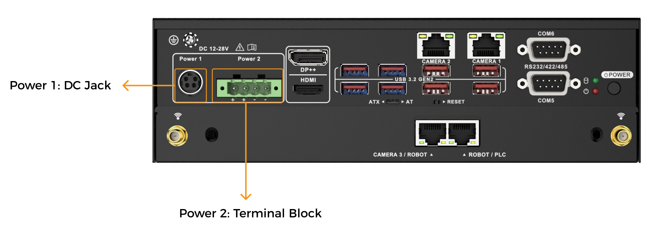
5.2. Power Connectors
There are two power connectors on the front panel. Power 1 connector is a DC Jack connector that supports ACC On signal. Power 2 connector is a 4-pin terminal that can directly connect to a power adapter. You can choose to use either of the two power connectors.
The supported power input voltages are:
-
Power 1 (DC Jack connector): 12–28 V DC
-
Power 2 (Terminal block): 12–28 V DC
When a power connector is connected to the power supply, the power LED indicator can indicate the status of the power.
| Power LED indicator | Description |
|---|---|
Off |
No power supply. |
On |
Power supply has been connected and the IPC has been powered on. |
5.2.1. Power 1 - 4-pin DIN Connector (DC Jack)
| This connector should be used when you are using a power adapter. |
This power connector should be connected to a 12–28 V DC power adapter. Please ensure that the provided power cord is correctly inserted into the power socket.

| Pin No. | Description | Pin No. | Description |
|---|---|---|---|
1 |
DC_IN1 |
2 |
GND |
3 |
DC_IN1 |
4 |
GND |
5.2.2. Power 2 - 4-pin Terminal Block
| This connector should be used when you are using a DIN rail power supply. |
This power connector connects the provided 4-pin terminal to the terminal block. The 4-pin terminal connects to a DIN rail power supply.
|
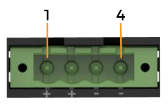
| Pin No. | Description | Pin No. | Description |
|---|---|---|---|
1 |
DC_IN2 |
2 |
DC_IN2 |
3 |
GND |
4 |
GND |
5.3. Ethernet Ports
The Ethernet ports allow the IPC to connect to an external network.
To connect the IPC to an external network, follow these steps:
-
Locate the Ethernet ports on the IPC.
-
Align the RJ45 connector on the Ethernet cable with one of the Ethernet ports.
-
Insert the RJ45 connector on the Ethernet cable into the Ethernet port.
Each Ethernet port has two status light-emitting diodes (LEDs). The Activity/Link LED indicates the link status or the activity of the port and the Speed LED indicates the connection speed of the port.

The following table shows the LED status of the Ethernet ports CAMERA 1, CAMERA 2, CAMERA 3/ROBOT and ROBOT/PLC.
| LED | Status | Description |
|---|---|---|
Activity/Link LED |
Off |
No link |
Yellow |
Linked |
|
Blinking |
Data is being sent/received |
|
Speed LED |
Off |
100 Mbps connection |
Orange |
1 Gbps connection |
|
Green |
2.5 Gbps connection |
|
If you are using an IPC delievered earlier, Ethernet ports of CAMERA 3/ROBOT and ROBOT/PLC use a different type of network interface card (NIC). Therefore, the LEDs on the Ethernet ports have different meanings. Each Ethernet port has two status LEDs, LED A and LED B. LED A indicates the status of the Power over Ethernet (POE) function of the port and LED B indicates the connection speed of the port. 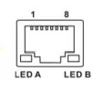
The following table shows the LED status of the Ethernet ports CAMERA 3/ROBOT and ROBOT/PLC.
|
5.4. Digital I/O Connector
The digital I/O connector provides programmable input and output for external devices.
The pinouts for the digital I/O connector are listed in the table below.
| Pin No. | Description | Pin No. | Description |
|---|---|---|---|
1 |
GND |
2 |
DIN0 |
3 |
DIN1 |
4 |
DIN2 |
5 |
DIN3 |
6 |
DIN4 |
7 |
DIN5 |
8 |
GND |
9 |
DOUT0 |
10 |
DOUT1 |
11 |
DOUT2 |
12 |
DOUT3 |
13 |
DOUT4 |
14 |
DOUT5 |
15 |
+5VS |
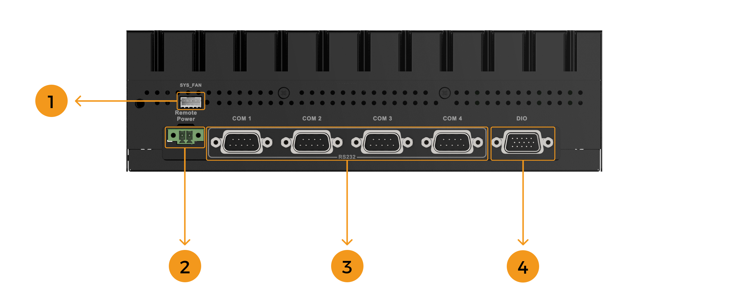
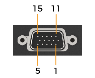
5.5. DB9 RS232/422/485 Serial Port Connector
The following figure shows RS232 (COM1 to COM4) and RS-232/422/485 (COM5 to COM6) connector pins.
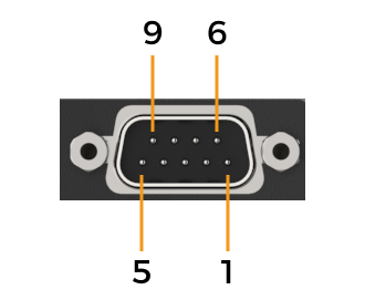
| Pin No. | RS232 | RS422 | RS485 |
|---|---|---|---|
1 |
DCD# |
TX- |
TX- |
2 |
Receiving data |
TX+ |
TX+ |
3 |
Sending data |
RX+ |
|
4 |
DTR# |
RX- |
|
5 |
GND |
||
6 |
DSR# |
||
7 |
RTS# |
||
8 |
CTS# |
||
9 |
RI |
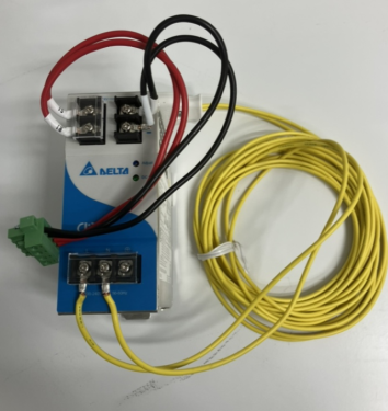
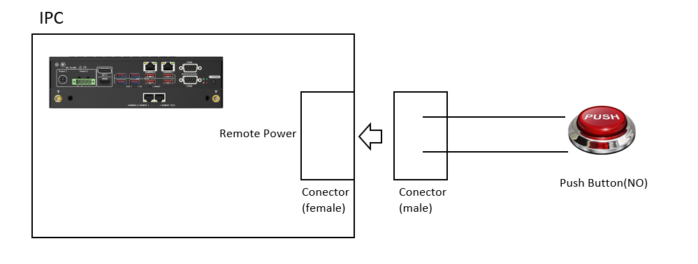
5.6. Remote Power Connector
The remote power switch connector can be connected to an external switch to remotely control the power switch.
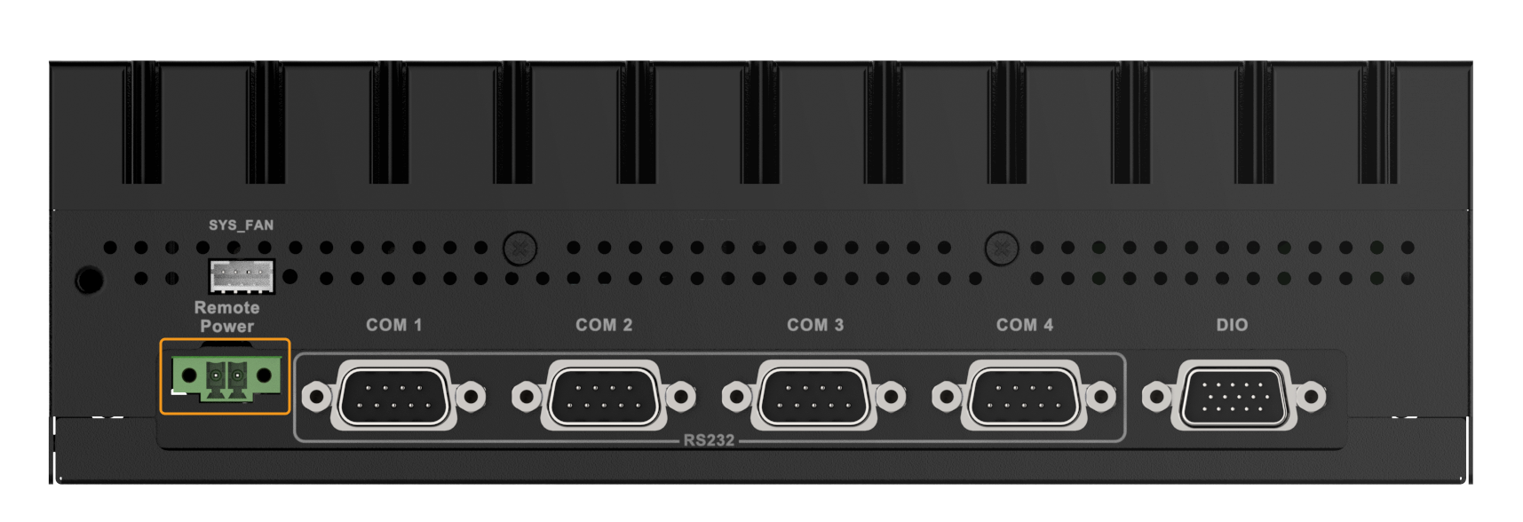
The remote power switch connector connects to the provided 2-pin terminal. When a short-circuit signal is applied to the 2-pin terminal, the IPC will automatically perform a shutdown operation.
The following figure shows possible connection scenarios where the power switch is remotely triggered by an external push-button switch or digital output (DO) signals from Programmable Logic Controllers (PLCs) or robots.
6. Power on/off the IPC
| Make sure a power supply with the correct input voltage is being fed into the IPC. Incorrect voltages applied to the system may cause damage to the internal electronic components and may also cause injury to the user. |
6.1. Power on the IPC
When the AT/ATX power mode switch is on the AT side, the IPC automatically starts up after the power connection.
When the AT/ATX power mode switch is on the ATX side, press the POWER button on the front panel.
When the IPC is successfully powered on, the power LED indicator should be solid red.
6.2. Power off the IPC
To power off the IPC, select on the IPC’s desktop.
When the IPC is successfully powered off, the power LED indicator should be off.
| Do not shut down the system by long-pressing the power button or cutting off power. Doing so may result in data loss or system crashes. |
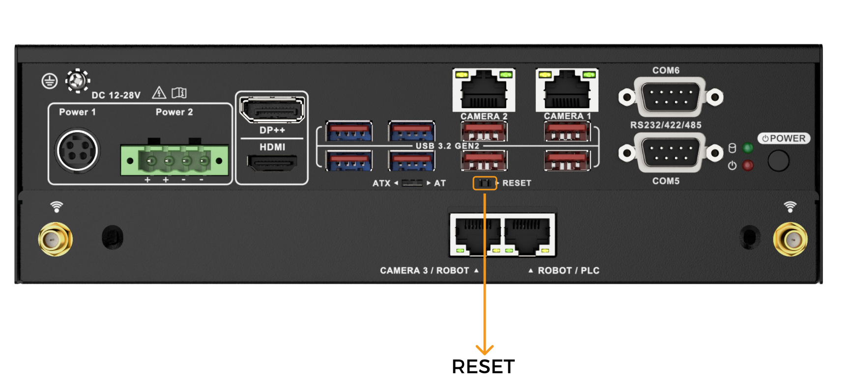
6.3. Restart the IPC
To restart the IPC, select on the IPC’s desktop.
When the system is unresponsive or frozen, or normal methods of restarting do not work, you can forcibly restart the IPC by pressing the RESET button on the front panel.
| The RESET button is small and located internally. When pressing it, please use a precision tool, such as a small screwdriver. |
7. Maintenance and Cleaning
When maintaining or cleaning this product, please follow the guidelines below.
7.1. Cleaning Precautions
Please read the following instructions carefully before cleaning any parts or components of this product:
-
The interior of this product does not require cleaning. Avoid allowing liquids to enter the interior of the product.
-
When using a vacuum cleaner to clean the product, be cautious with all removable small components.
-
Disconnect the power supply before cleaning this product.
-
When cleaning this product, avoid using solvents or chemicals that may cause allergic reactions.
-
Do not eat or smoke around this product.
7.2. Cleaning Tools
Some components of this product can only be cleaned using specialized tools. Below is a list of items to be used when cleaning this product.
-
Cloth - Use a soft, clean cloth to clean this product.
-
Water or rubbing alcohol - A cloth moistened with water or rubbing alcohol can be used to wipe the product.
-
Vacuum cleaner - Using a vacuum cleaner specifically designed for cleaning computers is one of the best methods to clean this product.
-
Cotton swabs - Cotton swaps moistened with rubbing alcohol or water are excellent tools for cleaning hard-to-reach areas. It is recommended to use cotton swabs that do not shed fibers, such as foam swabs, for cleaning.
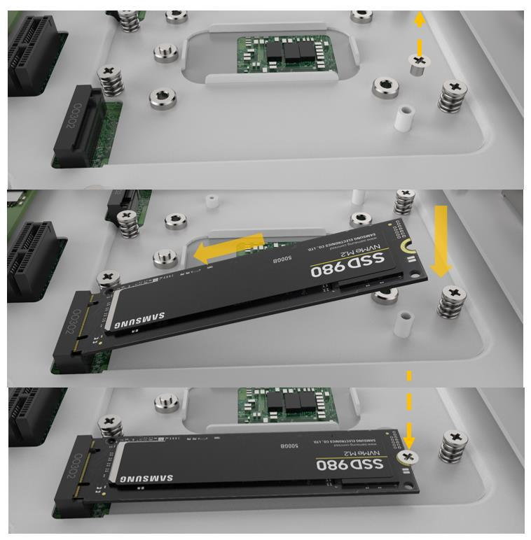
7.3. Replace Storage
This product supports two types of storage: an M.2 2280 M-key and a 2.5-inch SSD/HDD.
-
M.2 SSD installation
Remove the M.2 2280 reservation screw, install the M.2 2280 NVME card, and then secure the card with the reservation screw that was removed earlier.
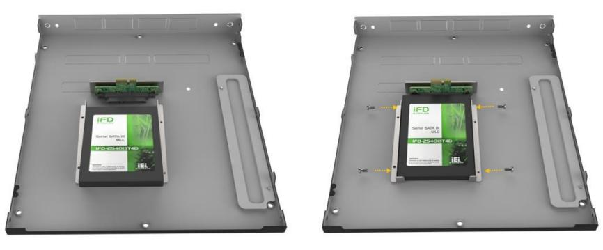
-
2.5" SSD/HDD installation
Place the hard drive into the hard drive holder, then use the four screws to lock the hard drive.
8. Troubleshooting
8.1. No Display on Boot
Symptom:
After powering on, the power LED and hard drive LED indicators are normal, but there is no display on the screen.
Possible causes:
-
The monitor is faulty.
-
The monitor cable is incompatible with the IPC’s interface.
-
The monitor cable is not connected to the HDMI or DP port on the discrete graphics card.
Solution:
-
Replace the monitor.
-
Replace the monitor cable.
-
If the IPC is equipped with a discrete graphics card, ensure that the monitor cable is connected to an HDMI or DP port on the discrete graphics card.
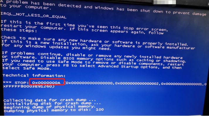
8.2. Automatic Shutdown or Reboot
Symptom:
During operation, the IPC automatically shuts down or reboots.
Possible causes:
-
A software has set a scheduled shutdown or reboot function.
-
An abnormal CPU temperature has caused the IPC to shut down or reboot.
-
A blue screen or other faults cause the IPC to reboot.
Solution:
-
Observe whether the automatic shutdown or reboot occurs at a fixed time.
If so, it may be caused by a software setting a scheduled shutdown or reboot function. Press the Delete key during boot to enter the BIOS, then wait for a period of time. If the IPC does not shut down or reboot at the fixed time, it can be confirmed that the issue is caused by the software’s scheduled shutdown or reboot setting. Please locate and disable this setting in the software.
-
If the issue is not caused by the software’s scheduled shutdown or reboot setting, please contact Mech-Mind Technical Support.
8.3. System Freeze or Lag
Symptom:
The screen freezes or the display becomes sluggish.
Possible causes:
-
Program conflicts cause the system to freeze or lag.
-
A cooling system failure causes the system to freeze or lag.
-
Electromagnetic interference causes the lag.
Solution:
-
Reboot the IPC. Rebooting usually resolves most system freeze issues. Press the Ctrl + Alt + Delete keys, select the power button at the lower right, and click reboot. If the system is unresponsive, press and hold the power button to force a reboot.
-
Close programs that consume excessive memory. Right-click the taskbar, select Task Manager, or use Ctrl + Shift + Esc to open it. Find the processes consuming high resources, right-click, and select End task to close them.
-
Check whether the cooling fan is running normally and whether the heatsink is blocked. If any abnormalities are found, please contact Mech-Mind Technical Support.
-
Identify sources of electromagnetic interference and take measures to control them, such as isolating the IPC from the interference source and ensuring proper grounding of the interference source.
9. Obtain Support
If you need technical support, please contact Mech-Mind Technical Support in any of the following means:
-
Email: service@mech-mind.net
-
Community: Mech-Mind Online Community
Appendix A: Error Beep Codes During Start
A.1. PEI Beep Codes
| Number of Beeps | Description |
|---|---|
1 |
Memory not installed. |
1 |
Memory was installed twice. (InstallPeiMemory routine in PEI Core called twice) |
2 |
Recovery started. |
3 |
DXEIPL was not found. |
3 |
DXE Core Firmware Volume was not found. |
4 |
Recovery failed. |
4 |
S3 Resume failed. |
7 |
Reset PPI is not available |
|
In the table above, all numbers of beeps were counted after all USB devices were removed. |
A.2. DXE Beep Codes
| Number of Beeps | Description |
|---|---|
1 |
Invalid password. |
4 |
Some of the Architectural Protocols are not available. |
5 |
No Console Output Devices are found. |
5 |
No Console Input Devices are found. |
6 |
Flash update failed. |
7 |
Reset protocol is not available. |
8 |
Platform PCI resource requirements cannot be met. |
|
In the table above, all numbers of beeps were counted after all USB devices were removed. |
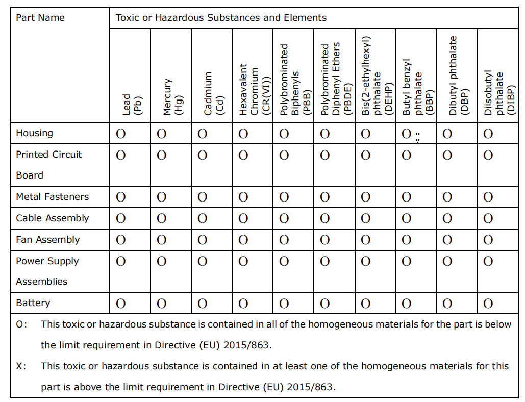
Appendix B: Hazardous Material Disclosure
The details provided in this appendix are to ensure that the product is compliant with the RoHS II Directive (2015/863/EU). The table below acknowledges the presence of small quantities of certain substances in the product and applies to RoHS II Directive (2015/863/EU).