PROFINET–Siemens SIMATIC S7 PLC Commands
This topic introduces the commands for PROFINET communication between a Siemens SIMATIC S7 PLC using the TIA Portal software and the Mech-Mind Vision System.
PROFINET–Siemens SIMATIC S7 PLC Commands
Start Mech-Vision Project
This command is used for applications that use Mech-Vision but not Mech-Viz. This command starts the Mech-Vision project that executes image capturing and performs vision recognition.
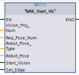
Parameters
Input parameters
-
Vision_Proj_Num: Mech-Vision project ID, which is the number before the project name in the Project List panel in Mech-Vision.
-
Req_Pose_Num: The number of vision points that Mech-Vision is requested to send, from 1 to 20, where 0 indicates “send all”.
-
Robot_Pose_Type: The type of robot pose to input to Mech-Vision. The value range is 0 to 3.
-
Robot_Pose: The pose received from the robot, value depends on the value of Robot_Pose_Type. Data type: two-dimensional array [0..1, 0..5] of DInt, array[0] is joint positions and array[1] is flange pose.
The following table explains the relationship between Robot_Pose_Type and Robot_Pose.
| Robot_Pose_Type value | Robot_Pose value | Description | Applicable Scenarios |
|---|---|---|---|
0 |
0, 0, 0, 0, 0, 0 |
The command does not send the robot pose to the Mech-Vision project. If the Path Planning Step is used in the Mech-Vision project, the start point of the planned path will be the Home point set in the path planning tool. |
This setting should be used if the camera is mounted in eye to hand mode and the project does not require images to be captured beforehand. |
1 |
Current joint positions and flange pose of the robot |
The robot joint positions and flange pose must be input to the Mech-Vision project. |
This setting should be used when the camera is mounted in eye in hand mode. This setting is recommended for most scenarios except those involving gantry robots. |
2 |
Current flange pose of the robot |
The robot flange pose must be input to the Mech-Vision project. |
This setting is recommended for scenarios involving gantry robots. |
3 |
Custom joint positions of the robot |
This command sends custom joint positions to the Mech-Vision project. This joint positions will be sent to the Path Planning Step in the Mech-Vision project as the start point, where the robot will move from this start point to the first waypoint of the planned path. |
This setting should be used if the camera is mounted in eye to hand mode and the project requires images to be captured beforehand. |
| Before assigning to the Robot_Pose array, multiply the floating-point numbers that represent joint positions or the robot flange pose by 10000 to convert the data to 32-bit signed integers. |
-
Start_Vision: Trigger the start of the Mech-Vision project at the rising edge.
-
Set_Edge: Store the value of Start_Vision in the last cycle to prevent unnecessary repetition of triggering.
Returned data from the CameraIO data block FromCamera:
-
STATUS_CODE: 1102 is returned if no error occurred. For other values, please refer to Status Codes and Troubleshooting for the corresponding error.
Example
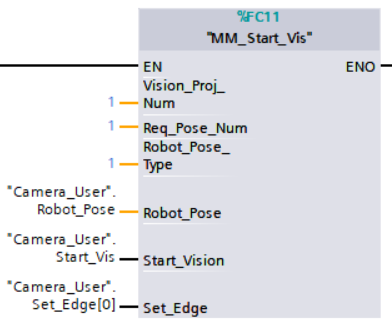
Example Description
When “Camera_User”.Start_Vis is at the rising edge, this example runs Mech-Vision project No.1, asks the Mech-Vision project to send over 1 vision point, and sends the robot joint positions when the Mech-Vision project is started as the image-capturing pose to the vision system.
Obtain Vision Target(s)
This command is used for applications that use Mech-Vision but not Mech-Viz. It obtains the vision result from the corresponding Mech-Vision project.
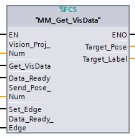
Parameters
Input parameters
-
Vision_Proj_Num: Mech-Vision project ID, which is the number before the project name in the Project List panel in Mech-Vision.
-
Get_VisData: Obtain vision points from Mech-Vision project when a rising edge occurs.
-
Data_Ready: Indicates the pose data is readable when receiving multiple sets of robot pose data.
-
Send_Pose_Num: The number of poses to be sent, from 0 to 20.
-
Set_Edge: Store the value of Start_Vision in the last cycle to prevent unnecessary repetition of triggering.
-
Data_Ready_Edge: This parameter does not need to be set by the user. It stores the value of “Data_Ready” in the last scan cycle to prevent unnecessary repetition of reading.
Output Parameters
-
Target_Pose: Obtained pose data (TCP) of waypoints. The data type is array[0..19, 0..5] of DInt. This array should be divided by 10000 before being used.
-
Target_Label: The label information of the object recognized by Mech-Vision. The data type is array[0..19] of UDInt. The returned values are integers.
Returned data from the CameraIO data block FromCamera:
-
STATUS_CODE: 1100 is returned if no error occurred. For other values, please refer to Status Codes and Troubleshooting for the corresponding error.
-
SEND_POSE_TYPE: The value returned by Mech-Vision via Command 102 is 2, which suggests that the type of poses obtained is in TCP.
Example
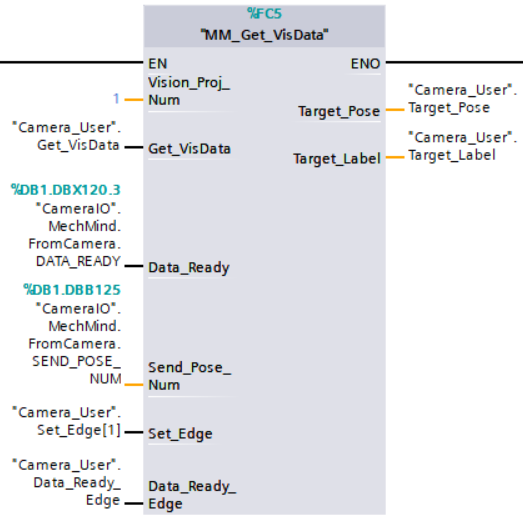
Example Description
When “Camera_User”.Get_VisData is at the rising edge, this example obtains the vision result from Mech-Vision project No.1.
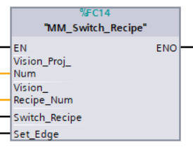
Switch Mech-Vision Recipe
This command specifies the parameter recipe used by the Mech-Vision project. Parameter recipes can be used to switch parameter settings, including point cloud model for matching, ROI, confidence threshold, etc, in the same Mech-Vision project when it is used to recognize different workpieces. This command must be called BEFORE MM_Start_Vis.
Parameters
Input parameters
-
Vision_Proj_Num: Mech-Vision project ID, which is the number before the project name in the Project List panel in Mech-Vision.
-
Vision_Recipe_Num: The ID of a parameter recipe in the Mech-Vision project, from 1 to 99.
-
Switch_Recipe: Switch the parameter recipe used by the Mech-Vision project when a rising edge occurs.
-
Set_Edge: Store the value of Start_Vision in the last cycle to prevent unnecessary repetition of triggering.
Returned data from the CameraIO data block FromCamera:
-
STATUS_CODE: 1107 is returned if no error occurred. For other values, please refer to Status Codes and Troubleshooting for the corresponding error.
Example
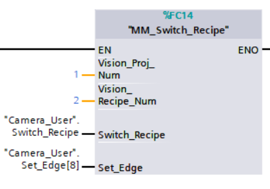
Example Description
When “Camera_User”.Switch_Recipe is at the rising edge, this example switches the parameter recipe used to No.2 in Mech-Vision project No.1.
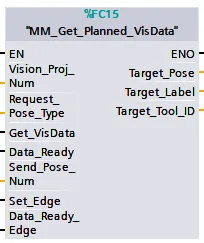
Get Result of Step “Path Planning” in Mech-Vision
After calling MM_Start_Vis, call this command to obtain the collision-free picking path planned by the “Path Planning” Step in the Mech-Vision project.
When using this command, set the Port Type parameter of the “Output” Step in the Mech-Vision project to “Predefined (robot path)”.
| Before executing this command, please set Req_Pose_Num in MM_Start_Vis to 0 to reduce the times of execution of this command. If Req_Pose_Num in MM_Start_Vis is set to 1, then every time this command is executed, only 1 waypoint is returned, and this command must be executed multiple times to obtain all the waypoints. |
Parameters
Input parameters
-
Vision_Proj_Num: Mech-Vision project ID, which is the number before the project name in the Project List panel in Mech-Vision.
-
Request_Pose_Type: This parameter specifies the type of waypoint poses returned by the “Path Planning” Step.
-
1: The waypoint poses are returned in the form of joint positions. -
2: The waypoint poses are returned in the form of TCP.
-
-
Get_VisData: Obtains the planned path from the “Path Planning” Step in Mech-Vision at the rising edge.
-
Data_Ready: Indicates the pose data is readable when receiving multiple sets of robot pose data.
-
Send_Pose_Num: The number of poses to be sent, from 0 to 20.
-
Set_Edge: Store the value of Get_VisData in the last cycle to prevent unnecessary repetition of triggering.
-
Data_Ready_Edge: This parameter does not need to be set by the user. It stores the value of “Data_Ready” in the last scan cycle to prevent unnecessary repetition of reading.
Output Parameters
-
Target_Pose: TCP of the waypoint. The data type is Array[0..19, 0..5] of DInt. This array should be divided by 10000 before being used.
-
Target_Label: The label information of the object recognized by Mech-Vision. The data type is Array[0..19] of UDInt. The returned values are integers.
-
Target_Tool_ID: The tool ID specified in the path planning tool.
Returned data from the CameraIO data block FromCamera:
-
STATUS_CODE: If there is no error, status code 1103 will be returned. Otherwise, the corresponding error code will be returned.
-
SEND_POSE_TYPE: The pose type of the waypoint, which is consistent with that of the Request_Pose_Type input parameter. 1 indicates JPs, while 2 indicates TCP.
-
VISUAL_POINT_INDEX: The position of the Vision Move Step, i.e., the move to the vision pose (usually the pose for picking the object) in the entire robot motion path.
Example
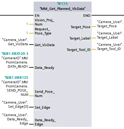
Example Description
When there is a rising edge on the variable Camera_User.Get_VisData, the path planned by the Mech-Vision project No.1 will be obtained in the form of joint positions.
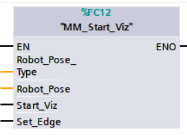
Start Mech-Viz Project
This command is for applications that use both Mech-Vision and Mech-Viz. It runs the corresponding Mech-Viz project (which triggers the corresponding Mech-Vision project to run), and then plans the path for picking.
Parameters
Input parameters
-
Robot_Pose_Type: The robot pose type specifies the type of the pose of the real robot to be input to the Mech-Viz project. The value range is from 0 to 2.
-
Robot_Pose: The pose received from the robot, value depends on the value of Robot_Pose_Type. Data type: two-dimensional array [0..1, 0..5] of DInt, array[0] is joint positions and array[1] is flange pose.
The following table explains the relationship between Robot_Pose_Type and Robot_Pose.
| Robot_Pose_Type value | Robot_Pose value | Description | Applicable Scenarios |
|---|---|---|---|
0 |
0, 0, 0, 0, 0, 0 |
No need to input the robot pose to Mech-Viz. The simulated robot in Mech-Viz moves from the initial pose JPs = [0, 0, 0, 0, 0, 0] to the first waypoint. |
Project is in the eye-to-hand mode. This setting is not recommended. |
1 |
Current joint positions and flange pose of the robot |
Robot joint positions and flange pose must be input to Mech-Viz. The simulated robot in Mech-Viz moves from the input JPs to the first waypoint. |
This setting is recommended for projects in the eye-in-hand mode. |
2 |
Specific joint positions of the robot |
The robot joint positions of a point determined by teaching must be input to Mech-Viz. The input joint positions are used to trigger Mech-Viz to plan the next path in advance while the robot is not in the camera capture region, as shown below. The simulated robot in Mech-Viz moves from the input joint positions to the first waypoint. |
This setting is recommended for projects in the eye-to-hand mode. |
|
The reason for setting Robot_Pose_Type to 2 when the project is in the eye-to-hand mode:
In the eye-to-hand mode, the camera can perform image capturing for the next round of path planning before the robot returns to the camera capture region and picking region, shortening the cycle time. If Robot_Pose_Type is set to 1, the robot’s current pose is sent to Mech-Viz. The simulated robot will move from the input pose to the first waypoint in the planned path, while the real robot might move to another point first, and then move to the first waypoint. Therefore, the path of the real robot may contain unpredicted collisions, leading to safety hazards. In conclusion, Robot_Pose_Type should be set to 2 for projects in the eye-to-hand mode. 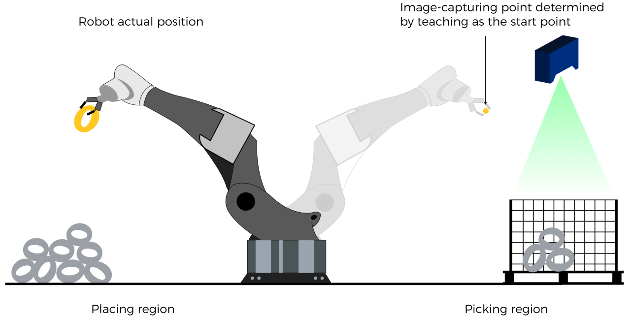
|
| Before assigning to the Robot_Pose array, multiply the floating-point numbers that represent joint positions or the robot flange pose by 10000 to convert the data to 32-bit signed integers. |
-
Start_Viz: Triggers the Mech-Viz project to run at the rising edge.
-
Set_Edge: Store the value of Start_Vision in the last cycle to prevent unnecessary repetition of triggering.
Returned data from the CameraIO data block FromCamera:
-
STATUS_CODE: 2103 is returned if Mech-Viz is successfully started and no error occurred. For other values, please refer to Status Codes and Troubleshooting for the corresponding error.
Example
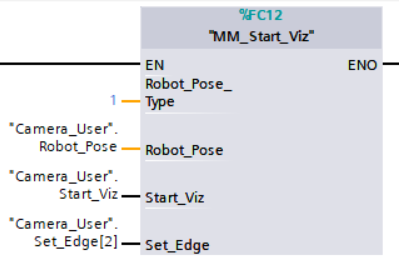
Example Description
When the variable * “Camera_User”.Start_Viz* is at the rising edge, this example runs the corresponding Mech-Viz project, and sends the current joint positions of the robot to the vision system.
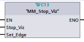
Stop Mech-Viz Project
This command is used to stop Mech-Viz project. This command is only needed if the Mech-Viz project falls into an infinite loop or cannot be stopped normally.
Parameters
Input parameters
-
Stop_Viz: Stop the execution of the Mech-Viz project at the rising edge.
-
Set_Edge: Store the value of Start_Vision in the last cycle to prevent unnecessary repetition of triggering.
Returned data from the CameraIO data block FromCamera:
-
STATUS_CODE: 2104 is returned if Mech-Viz is successfully stopped and no error occurred. For other values, please refer to Status Codes and Troubleshooting for the corresponding error.
Example
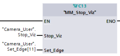
Example Description
When “Camera_User”.Stop_Viz is at the rising edge, this example stops the execution of the Mech-Viz project.
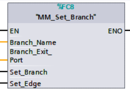
Select Mech-Viz Branch
This command is used to select along which branch the Mech-Viz project should proceed. Such branching is achieved by adding Branch by Msg Step(s) to the Mech-Viz project. This command specifies which exit port such Step(s) should take. MM_Start_Viz should be called BEFORE this subprogram. When executing the “Branch by Msg” Step, Mech-Viz waits for the exit port No. sent by Command 203.
Parameters
Input parameters
-
Branch_Name: Step ID of the Branch by Msg Step, which is a positive integer.
-
Branch_Exit_Port: The number of the exit port to take, from 1 to 99.
-
This parameter value should be 1 greater than the exit port number displayed in the Mech-Viz Step. For example, the port 0 displayed in the interface corresponds to Branch_Exit_Port 1.
-
Branch_Name, Branch_Exit_Port, and Index_Name and Index_Counter in MM_Set_Index correspond to the same VIZ_TASK_NAME and VIZ_TASK_VALUE tags in the CameraIO data block respectively. If the set values are different, they cannot take effect at the same time.
-
-
Set_Branch: Specify the port which Branch by Msg Step should take.
-
Set_Edge: Store the value of Start_Vision in the last cycle to prevent unnecessary repetition of triggering.
Returned data from the CameraIO data block FromCamera:
-
STATUS_CODE: 2105 is returned if the branch is successfully selected and no error occurred. For other values, please refer to Status Codes and Troubleshooting for the corresponding error.
Example
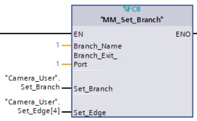
Example Description
When “Camera_User”.Set_Branch is at the rising edge, this example tells Mech-Viz to take exit port 1 for the Branch by Msg Step whose Step ID is 1.
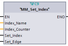
Set Move Index
This command sets the value for the Current Index parameter of Steps. Steps that have this parameter include Move by List, Move by Grid, Custom Pallet Pattern, and Smart Pallet Pattern. MM_Start_Viz must be called BEFORE this command.
Parameters
Input parameters:
-
Index_Name: The ID of the Step, an integer.
-
Index_Counter: The index value that should be set the next time this Step is executed. When this command is sent, the current index value in Mech-Viz will become the parameter value minus 1. When the Mech-Viz project runs to the Step specified by this command, the current index value in Mech-Viz will be increased by 1 to become the parameter’s value.
Index_Name、Index_Counter, and Branch_Name and Branch_Exit_Port in MM_Set_Branch correspond to the same VIZ_TASK_NAME and VIZ_TASK_VALUE tags in the CameraIO data block respectively. If the set values are different, they cannot take effect at the same time. -
Set_Index: The trigger signal to set the index. The rising edge does the trigger.
-
Set_Edge: Store the value of Start_Vision in the last cycle to prevent unnecessary repetition of triggering.
Returned data from the CameraIO data block FromCamera:
-
STATUS_CODE: 2106 is returned if the index is successfully set and no error occurred. For other values, please refer to Status Codes and Troubleshooting for the corresponding error.
Example
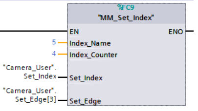
Example Description
When “Camera_User”.Set_Index is at the rising edge, this example sets the Current Index value to 3 for the Step in the Mech-Viz project whose Step ID is 5. When the Step is executed, the Current Index value will be added 1 and become 4.
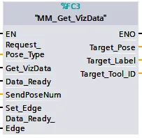
Get Planned Path
This command obtains the planned path from Mech-Viz.
Parameters
Input parameters:
-
Request_Pose_Type: Pose type of the waypoints to be obtained.
-
1: The pose type returned by Mech-Viz is joint positions.
-
2: The pose type returned by Mech-Viz is joint positions.
-
-
Get_VizData: Obtains the planned path from Mech-Viz at the rising edge.
-
Data_Ready: Indicates the pose data is readable when receiving multiple sets of robot pose data.
-
Send_Pose_Num: The number of waypoints returned by Mech-Viz, from 0 to 20.
-
Set_Edge: Store the value of Start_Vision in the last cycle to prevent unnecessary repetition of triggering.
-
Data_Ready_Edge: This parameter does not need to be set by the user. It stores the value of “Data_Ready” in the last scan cycle to prevent unnecessary repetition of reading.
Output Parameters
-
Target_Pose: Obtained pose data (TCP) of waypoints. The data type is array[0..19, 0..5] of DInt. This array should be divided by 10000 before being used.
-
Target_Label: The label information of the object recognized by Mech-Vision. The data type is array[0..19] of UDInt. The returned values are integers.
-
Target_Tool_ID: The tool ID specified in the Mech-Viz project.
Returned data from the CameraIO data block FromCamera:
-
STATUS_CODE: 2100 is returned if no error occurred. For other values, please refer to Status Codes and Troubleshooting for the corresponding error.
-
SEND_POSE_TYPE: The pose type of the target picking point, which is consistent with that of the Request_Pose_Type input parameter. 1 indicates JPs, while 2 indicates TCP.
-
VISUAL_POINT_INDEX: The position of the vision point, which is generated from the “Vision Move” Step, in the planned path.
Example
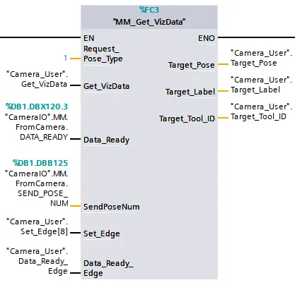
Example Description
When “Camera_User”.Get_VizData is at the rising edge, this example obtains the planned path from Mech-Viz in the form of TCPs.
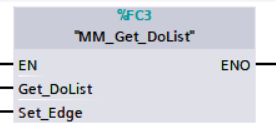
Get DO Signal List
This command obtains the planned DO Signal list for controlling multiple sections of a sectioned vacuum gripper. MM_Get_VizData must be used BEFORE this command.
Please refer to the suction_zone.viz template in XXXX/Communication Component-xxx/tool/viz_project/suction_zone, and set the suction cup configuration file before calling the command.
|
Parameters
Input parameters:
-
Get_DoList: Obtain the planned DO signal list from Mech-Viz at the rising edge.
-
Set_Edge: Store the value of Start_Vision in the last cycle to prevent unnecessary repetition of triggering.
Returned data from the CameraIO data block FromCamera:
-
STATUS_CODE: 2102 is returned if the DO signal list is successfully obtained and no error occurred. For other values, please refer to Status Codes and Troubleshooting for the corresponding error.
-
DO_LIST: DO signals returned by Mech-Viz. DO_LIST consists of 8 (0 to 7) bytes. Each byte consists of 8 bits (0 to 7). Therefore, the 0 to 63 bits of DO_LIST correspond to 0 to 63 DO signals. For example, the 0th position in the DO list represents the 0 DO signal. If the value of this position is True, the DO signal is valid. If the value is False, the DO signal is invalid.
Example
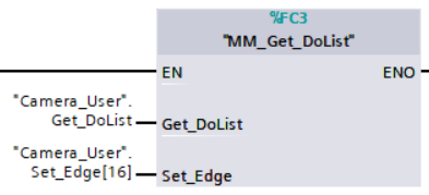
Example Description
In this example, when the parameter “Camera_User”.Get_DoList has a rising edge, the DO values retrieved from Mech-Viz will be stored in the DO list.
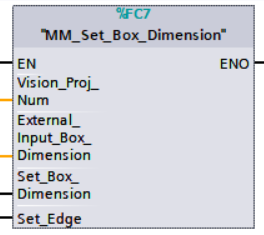
Input Object Dimensions to Mech-Vision
This command inputs object dimensions to the Mech-Vision project.
Parameters
Input parameters
-
Vision_Proj_Num: The Project ID of the Mech-Vision project; you can check the project ID before the project name in the Project List panel in Mech-Vision.
-
External_Input_Box_Dimension: The unit is in mm, for example, the dimensions of a box (length, width, height). Multiply each dimension by 10000 and then assign the results to External_Input_Box_Dimension[0-2].
External_Input_Box_Dimension here and External_Input_Pose in MM_Set_Pose correspond to the same EXT_INPUT_DATA tag of the CameraIO data struct. If the set values are different, they cannot take effect at the same time. -
Set_Box_Dimension: Inputs the object dimensions in the Mech-Vision project dynamically at the rising edge.
-
Set_Edge: Store the value of Start_Vision in the last cycle to prevent unnecessary repetition of triggering.
Returned data from the CameraIO data block FromCamera:
-
STATUS_CODE: 1108 is returned if no error occurred. For other values, please refer to Status Codes and Troubleshooting for the corresponding error.
Example
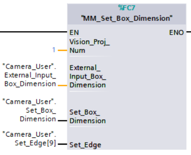
Example Description
When “Camera_User”.Set_Box_Dimension is at the rising edge, this example sets the object dimensions in the Read Object Dimensions Step in the Mech-Vision project No.1 to the values in External_Input_Box_Dimension.
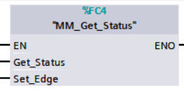
Get Software Status
This command is currently capable of checking whether Mech-Vision ready to run projects. In the future, this command can be used for obtaining the software execution status.
Parameters
Input parameters:
-
Get_Status: Check whether Mech-Vision is ready to run projects at the rising edge.
-
Set_Edge: Store the value of Start_Vision in the last cycle to prevent unnecessary repetition of triggering.
Returned data from the CameraIO data block FromCamera:
-
Status code: Represent the software status.
Example
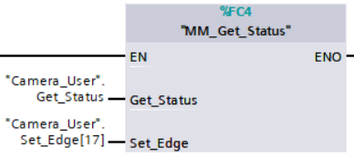
Example Description
When “Camera_User”.Get_Status is at the rising edge, this example checks the status code and stores it in STATUS_CODE.
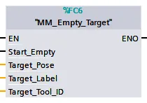
Clear Target Data
This command clears the obtained data stored in Target_Pose, Target_Label, and Target_Tool_ID.
Parameters
Input parameters:
-
Start_Empty: Clear the data stored in Target Pose, Target Label, and Target Tool ID when it is set.
-
Target_Pose: Obtained target poses.
-
Target_Label: Obtained labels.
-
Target_Tool_ID: The obtained tool ID.
Example
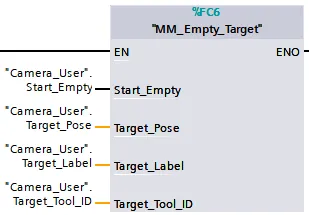
Example Description
In this example, when the variable “Camera_User”.Start_Empty is set to 1, the acquired data in Target Pose, Target Label, and Target Tool ID will be cleared.
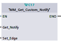
Get Message from Notify Step
After the Mech-Vision or Mech-Viz project is triggered, this command can be called to get message from the “Notify” Step. For now, the message can only be an integer.
| When the “Notify” Step is executed in the Mech-Vision or Mech-Viz project, the message remains in the buffer of the vision system for only 1 second. Therefore, users should consider the timing of calling this command to ensure successful message retrieval. Additionally, after the PLC receives the message, the program should trigger the variable “CameraIO”.MM.ToCamera.CLEAR_NOTIFY to clear the register data. |
Parameters
Input parameters:
-
Get_Notify: Get a message from the “Notify” Step, triggered at a rising edge.
-
Set_Edge: Store the value of Start_Vision in the last cycle to prevent unnecessary repetition of triggering.
Returned data from the CameraIO data block FromCamera:
-
NOTIFY_MSG: The message from the Notify Step, which is an integer.
Example
For example, the message set in the “Notify” Step is 777, and the PLC is obtaining a message in the automatic mode.
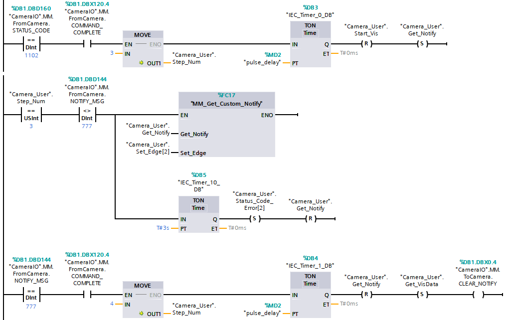
Example Description
In this example, when “Camera_User”.Step_Num is set to 3 in the automatic mode, the value of “CameraIO”.MM.FromCamera.NOTIFY_MSG is not 777. After “MM_Get_Custom_Notify” is enabled, when the “Camera_User”.Get_Notify variable is at the rising edge, the program retrieves the message from the “Notify” Step. If the message retrieval was successful, the value of “CameraIO”.MM.FromCamera.NOTIFY_MSG changes to 777. Otherwise, if the value remains unchanged, the PLC will prompt an error after 3 seconds.
Appendix
Description of the Status Codes
Please refer to Status Codes and Troubleshooting for detailed information.