Set up Standard Interface Communication with YASKAWA
This guide shows how to load the Standard Interface program files to a YASKAWA robot, and set up the Standard Interface communication between Mech-Mind Vision System and the robot.
| In this section, you will load the Standard Interface program and the configuration files to the robot system to establish the Standard Interface communication between the vision system and the robot. |
Preparation
Check Controller and Software Compatibility
-
Confirm that the robot is a 6-axis YASKAWA robot. In this guide, YASKAWA_GP8 is used.
-
Confirm that the robot controller model and the system version meet the requirements below.
Robot controller System version DX200
DN3.16.00A-00
YRC1000
YAS2.94.00-00
YRC1000micro
YBS2.31.00-00
In this guide, YRC1000 (YAS2.94.00-00) is used. -
Confirm that the Ethernet option has been enabled for the YASKAWA robot.
Click here for instructions
-
Press and hold the MAIN MENU key on the teach pendant, and power on the robot to enter the maintenance mode.
If the robot is already started, please restart the robot while pressing the MAIN MENU key on the teach pendant. 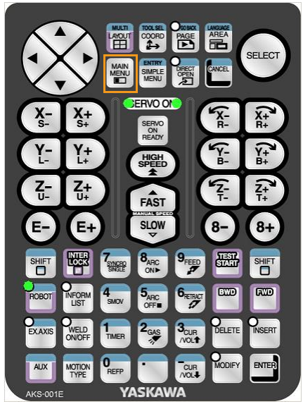
-
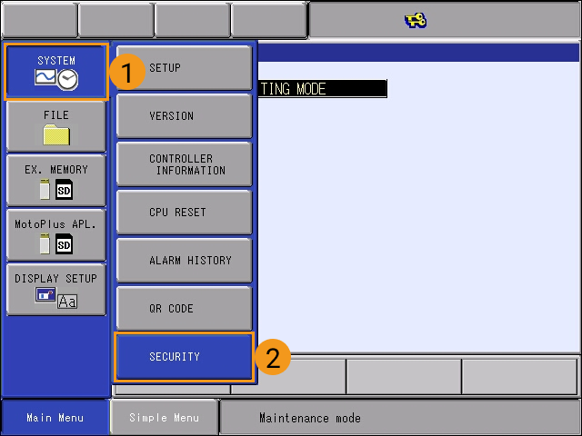
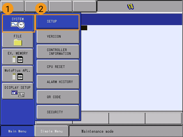
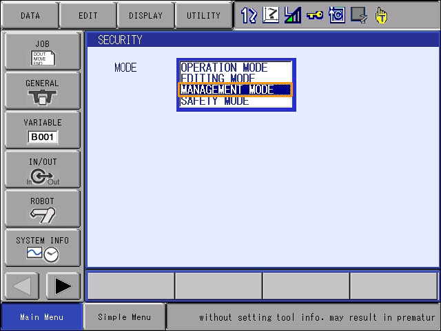
In the maintenance mode, select .
-
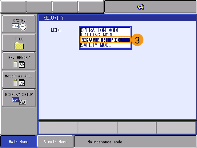
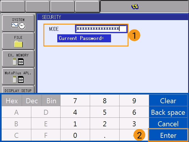
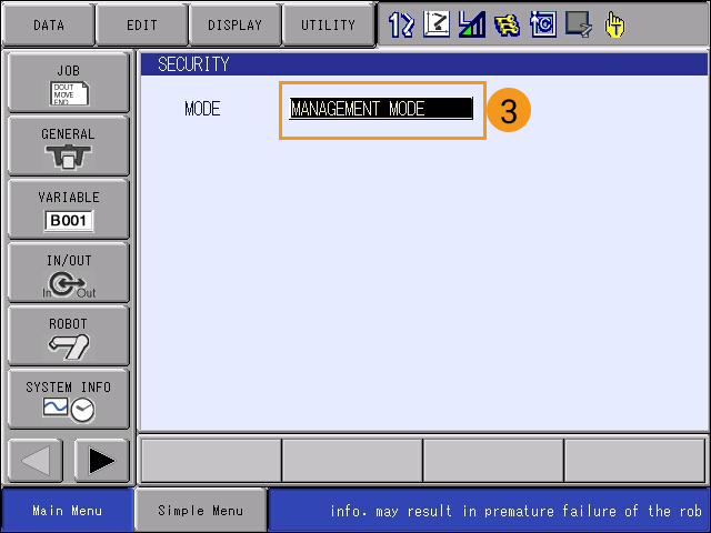
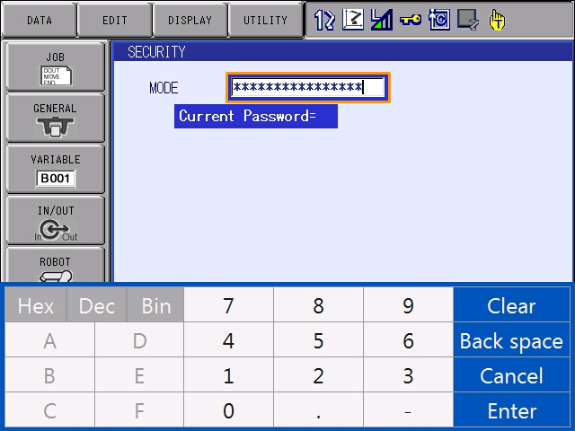
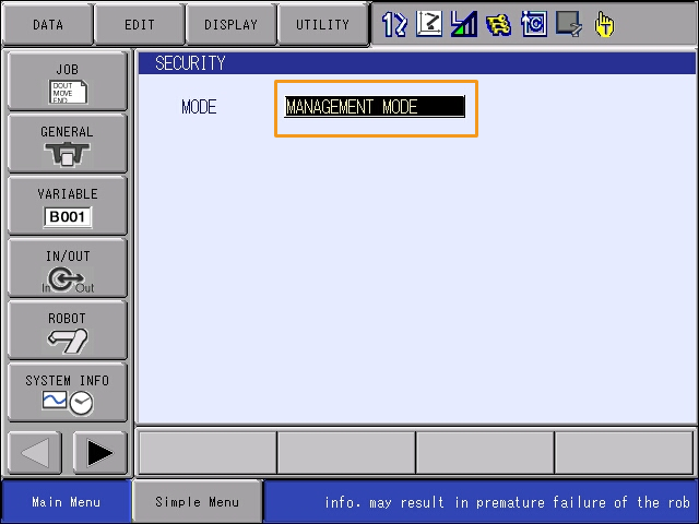
Enter the password (which is sixteen 9s by default), and then select Enter to enter the MANAGEMENT MODE.
-
In Main Menu, select .
-
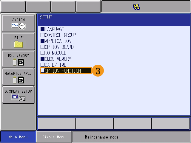
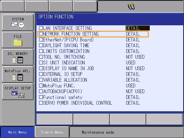
At the OPTION FUNCTION interface, select DETAIL of NETWORK FUNCTION SETTING, and then press SELECT on the teach pendant to enter the NETWORK FUNCTION SETTING interface.
-
Check whether the status of ETHERNET is displayed as USED.
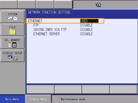
If the status is NOT USED, please contact the robot manufacturer for support.
-
-
Confirm that the MotoPlus option has been enabled for the YASKAWA robot.
Click here for instructions
-
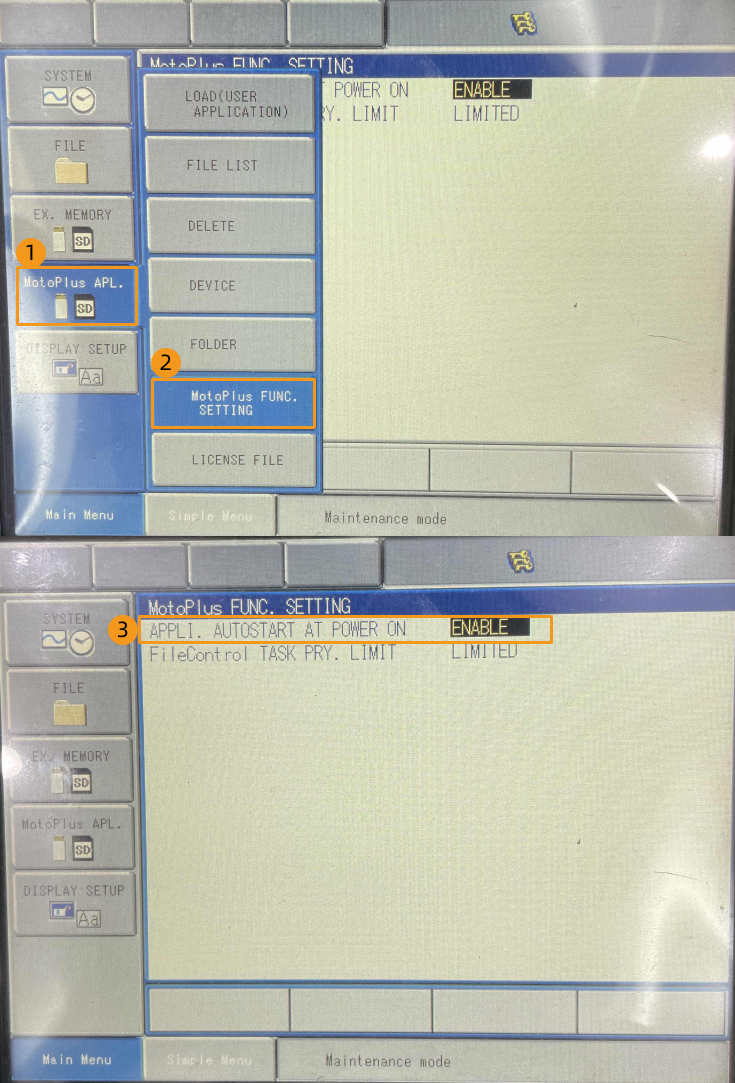
In the MANAGEMENT MODE of the maintenance mode, select on the Main Menu.
-
On the MotoPlus FUNC. SETTING interface, check whether the status of APPLI. AUTOSTART AT POWER ON is ENABLE.
-
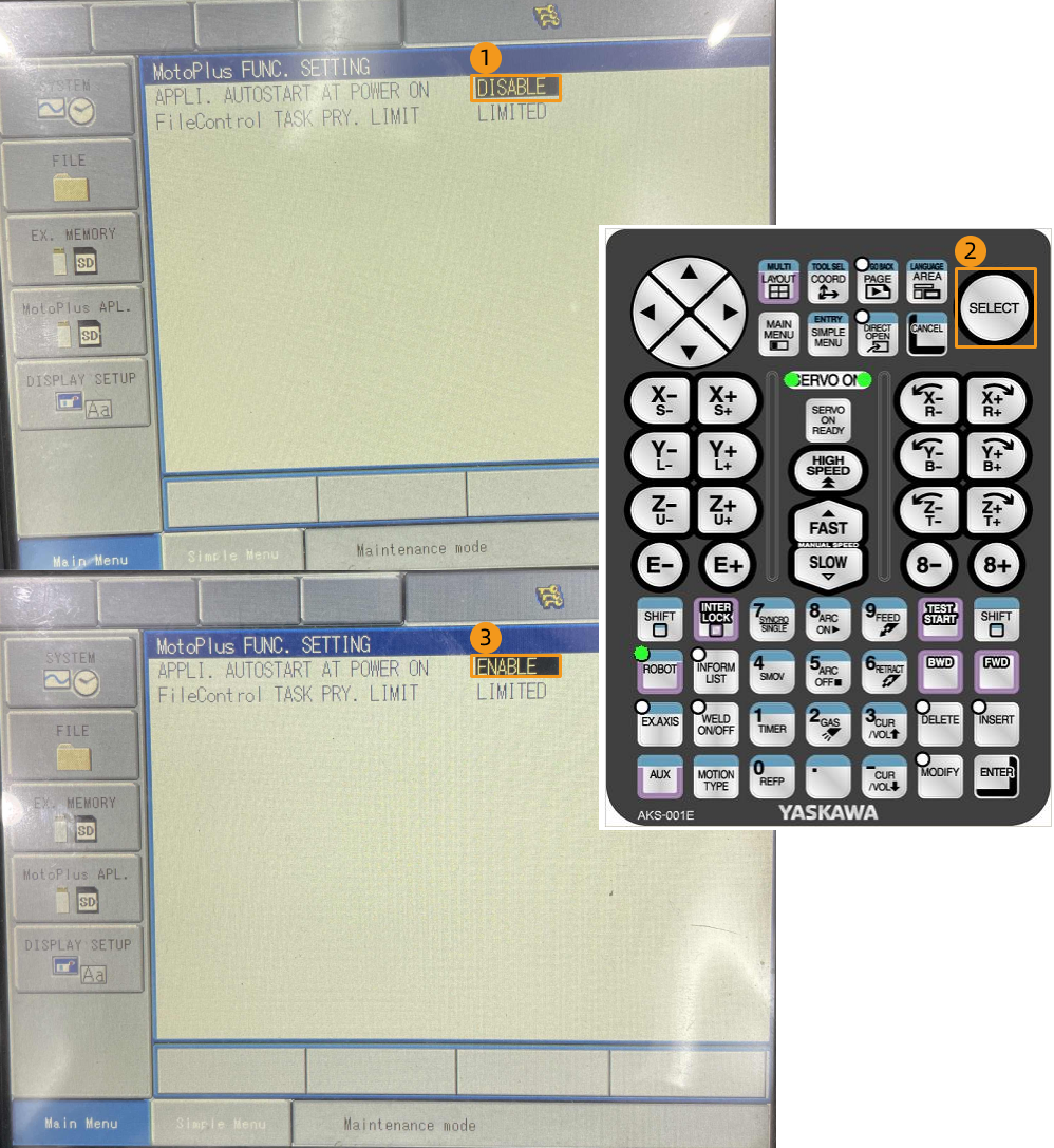
If the status is DISABLE, select DISABLE, and press SELECT on the teach pendant to switch the status to ENABLE.
-
|
If the preceding conditions cannot be met, the vision system cannot communicate with the robot through the Standard Interface. Please contact the robot manufacturer for support. |
Set up the Network Connection
-
If you are using the YRC1000 controller, plug one end of the Ethernet cable into the network port of the IPC and the other end into the LAN2 (CN106) port on the CPU board of the robot controller.
-
If you are using the DX200 controller, plug one end of the Ethernet cable into the network port of the IPC and the other end into the CN104 port on the CPU board of the robot controller.
-
For the YRC1000 controller:
-
The LAN1 port is only used to connect the teach pendant and cannot be used to connect the IPC Ethernet cable.
-
If the LAN2 port is occupied, use LAN3 instead, to connect the IPC Ethernet cable.
-
-
-
Make sure that the IP address of the YASKAWA robot and that of the IPC are in the same subnet.
Click here for instructions
-
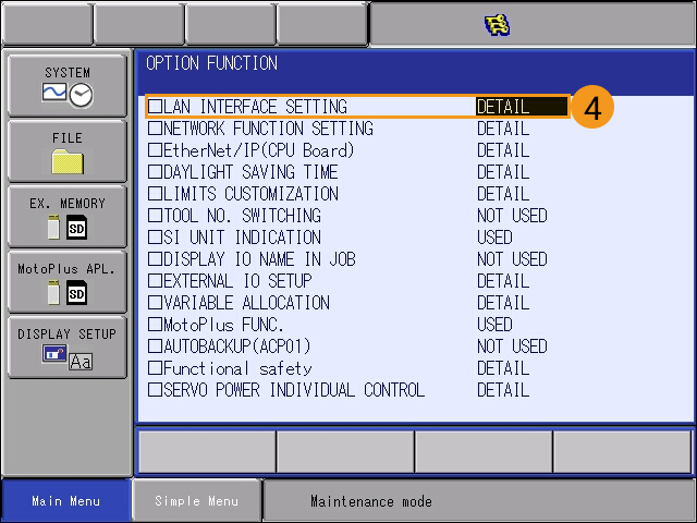
At the MANAGEMENT MODE of the maintenance mode, select on the Main Menu. In the OPTION FUNCTION interface, select LAN INTERFACE SETTING.
-
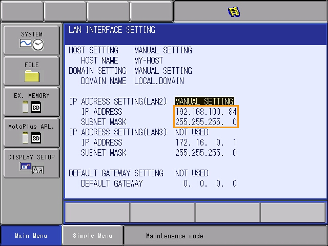
Check the IP address of the robot (i.e., the IP address of LAN2).
-
Make sure that the IP address of the robot and that of the IPC are in the same subnet. If they are not in the same subnet, please refer to the section Set the IP Addresses on the IPC to modify the IP address of the IPC.
-
Set up Robot Communication Configuration
-
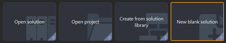
Open Mech-Vision, and you may enter different interfaces. Create a new solution according to the instructions below.
-
If you have entered the Welcome interface, click New blank solution.
-
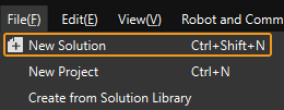
If you have entered the main interface, click on the menu bar.
-
-
Click Robot Communication Configuration on the toolbar of Mech-Vision.
-
In the Robot Communication Configuration window, complete the following configurations.
-
Click the Select robot drop-down menu, and select Listed robot. Click Select robot model, and select the robot model that you use. Then, click Next.
-
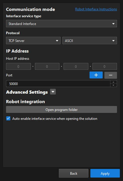
In the Communication mode section, select Standard Interface for Interface service type, TCP Server for Protocol, and ASCII for the protocol format.
-
It is recommended to set the port number to 50000 or above. Ensure that the port number is not occupied by another program.
-
Under Robot integration, click Open program folder.
The files needed for subsequent loading will be copied from this folder. Do not close this folder. -
(Optional) Select Auto enable interface service when opening the solution.
-
Click Apply.
-
-
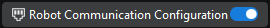
On the main interface of Mech-Vision, make sure that the Robot Communication Configuration switch on the toolbar is flipped and has turned blue.
Prepare the Program Files
-
Plug the flash drive into the USB port of the IPC.
Please ensure that your flash drive is formatted in advance and the file system of the flash drive is FAT32.
-
On the IPC, copy the JBI folder and the mm_module_yrc1000.out file in the opened program folder (the
YASKAWAfolder) to the root directory of the formatted empty flash drive, and then unplug the flash drive.-
You can also find the program folder in the
Communication Component/Robot_Interface/YASKAWApath in the installation directory of Mech-Vision and Mech-Viz. -
If you are using the DX200 controller, copy the JBI folder and the mm_module_dx200.out file to the root directory of the empty USB flash drive which is formatted already.
-
mm_module_yrc1000.out: the background program file (for YRC1000 controllers).
-
mm_module_dx200.out: the background program file (for DX200 controllers).
-
JBI: the folder storing foreground program files.
-
sample: the folder for storing example program files.
-
Make Sure That No Program Is Running in MotoPlus
Before you load the robot program files to the robot, make sure that no other MotoPlus programs are running.
-
If no programs are running, skip this section.
-
If there are any running programs, delete those application programs.
Click here for instructions
-
In the MANAGEMENT MODE of the maintenance mode, select on the Main Menu.

-
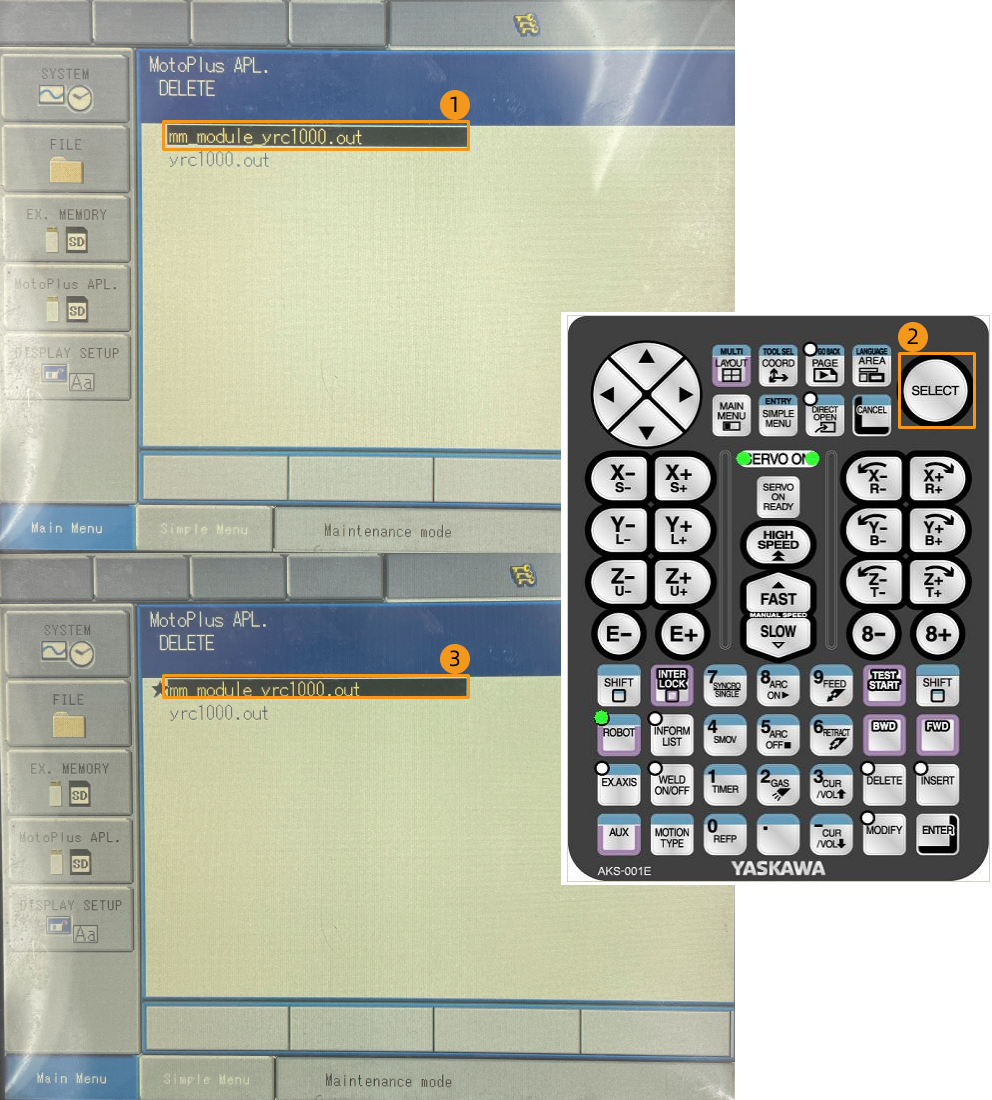
On the MotoPlus APL. DELETE interface, select the program file to be deleted, and then press SELECT on the teach pendant to select this file.
-
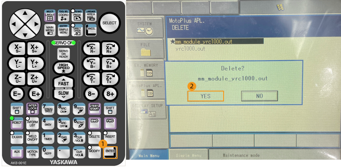
Press ENTER on the teach pendant, and press the YES button on the pop-up dialog box to delete the program.
-
Load the Program Files
Load the Background Program File to the Robot
-
Plug the USB flash drive into the USB port on the rear panel of the teach pendant.
-
Press and hold the MAIN MENU key on the teach pendant, and power on the robot to enter the maintenance mode.
If the robot is already started, please restart the robot while pressing the MAIN MENU key on the teach pendant. -
In the maintenance mode, select .
-
Enter the password (which is sixteen 9s by default), and then select Enter to enter the MANAGEMENT MODE.
-
Select on the Main Menu.
-
Select .
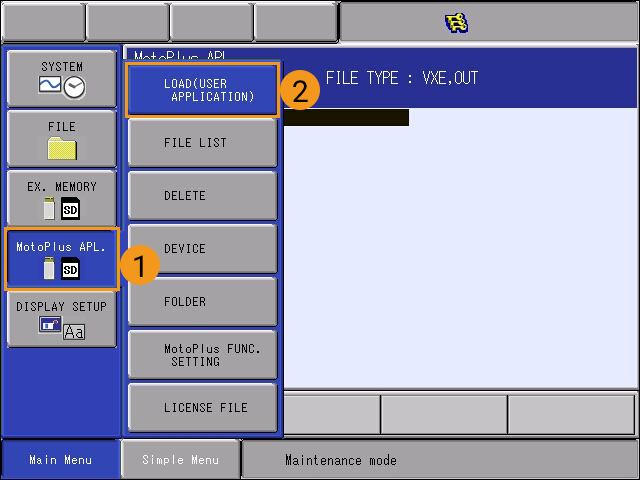
-
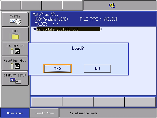
Select mm_module_yrc1000.out. Press ENTER on the teach pendant and then select YES to start loading.
If you are using the DX200 controller, you need to select mm_module_dx200.out in this step. 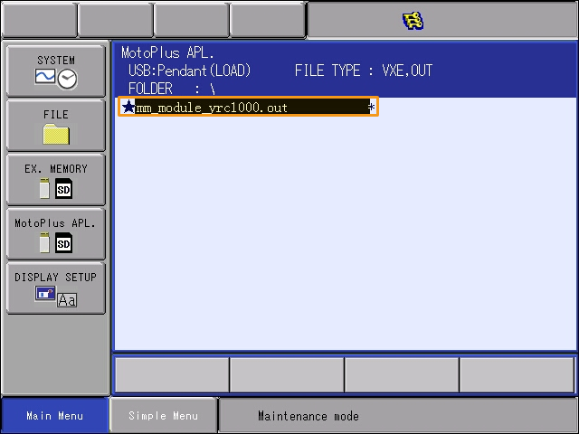
-
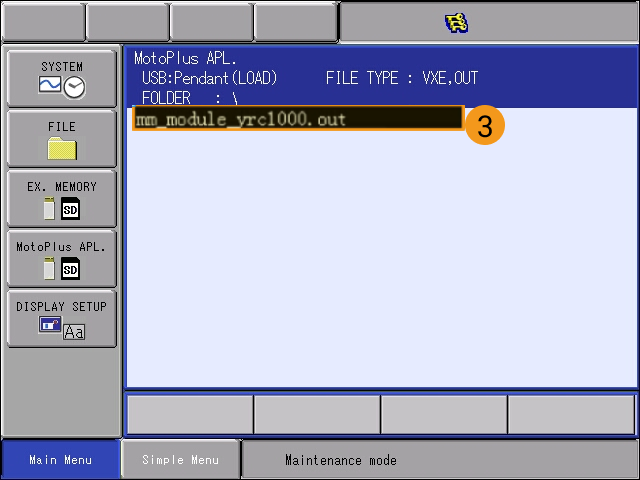
After the loading completes, select . If you can see the background program file (mm_module_yrc1000.out) in the file list, the loading of the background program file is successful.
If you are using the DX200 controller, you will see the background program mm_module_dx200.out here. 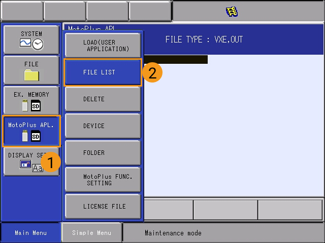
-
After you have loaded the background program file, turn the power switch to restart the controller to enter the online mode.
You need to load the foreground program files and the example program files under the online mode. Therefore, you need to perform this operation after loading the background program file.
Load the Foreground Program Files to the Robot
-
Under the online mode, select on Main Menu of the teach pendant.
-
Select MANAGEMENT MODE in the drop-down menu.
-
Enter the password. By default, the password is sixteen 9s.
Select Enter in the lower-right corner of the teach pendant screen to enter the management mode.
-
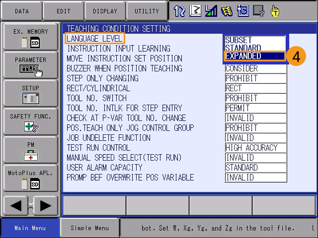
Select the right-arrow
 button in the lower-left corner of the teach pendant screen. Then, select , and select EXPANDED in the drop-down menu of LANGUAGE LEVEL.
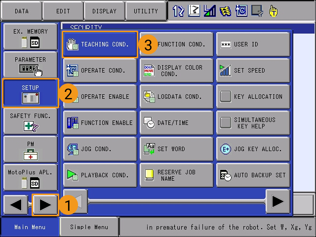
-
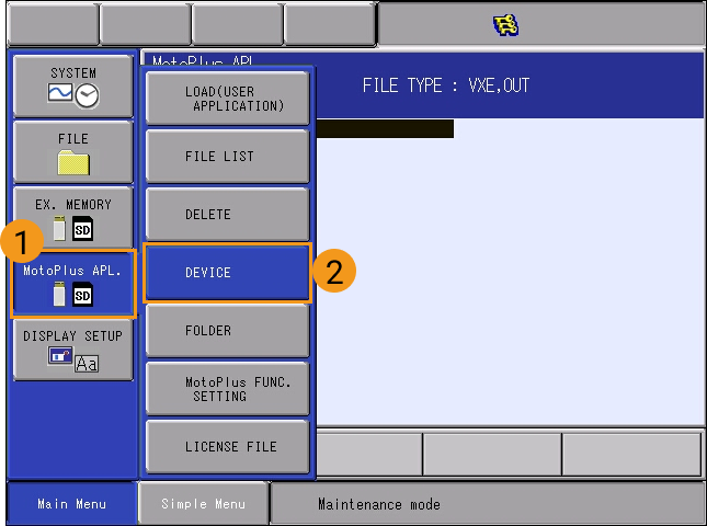
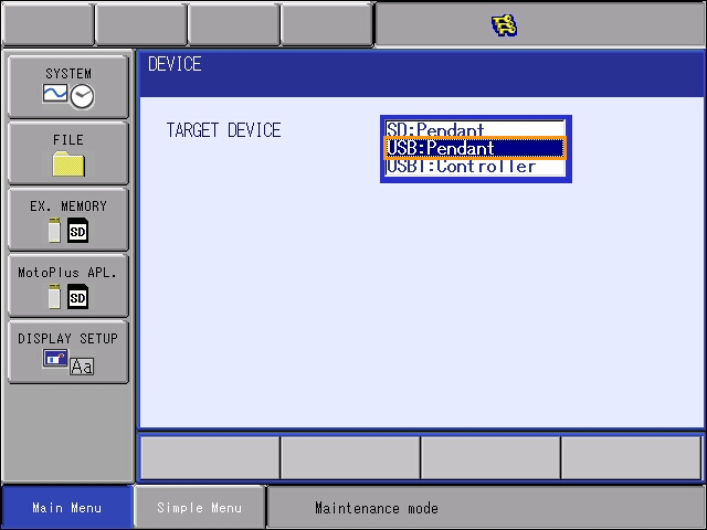
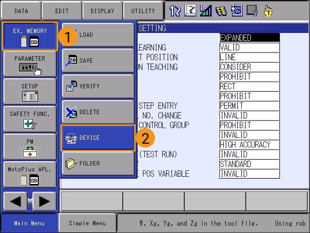
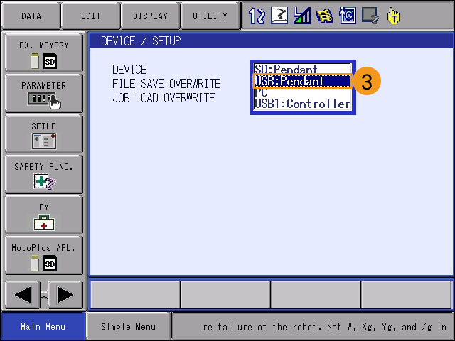
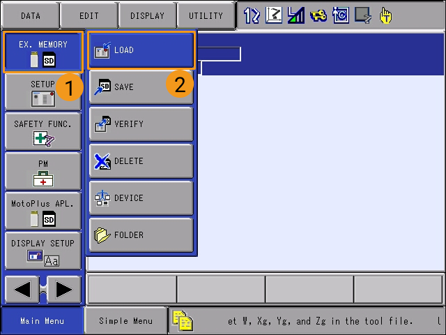
Select , and then select USB:Pendant for DEVICE.
-
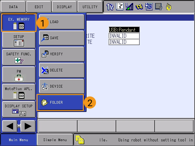
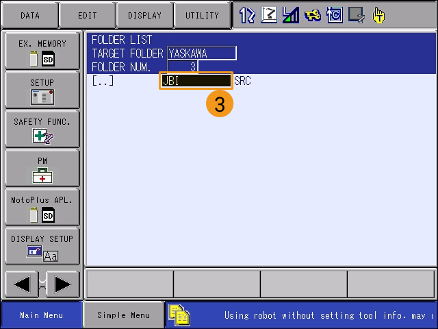
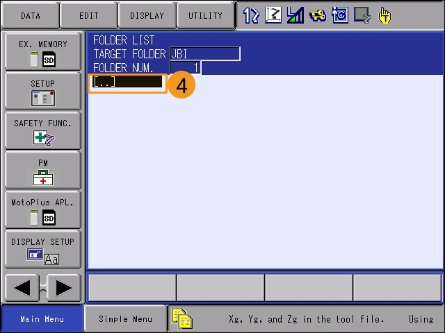
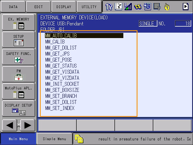
Select . In the FOLDER LIST, select and enter the JBI folder.
-
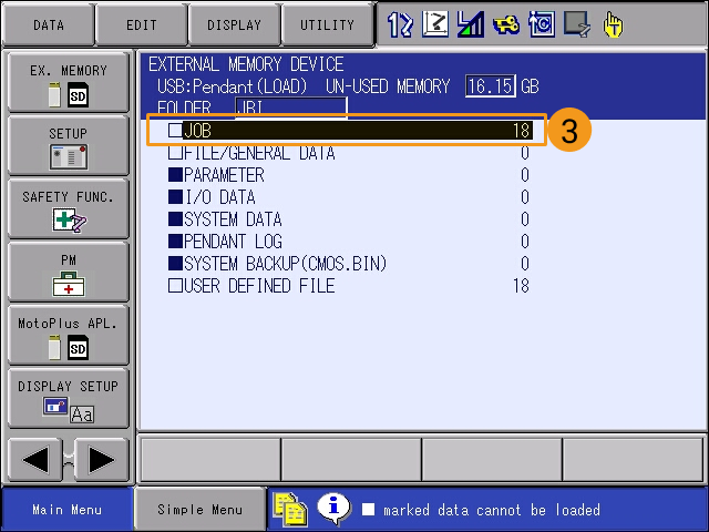
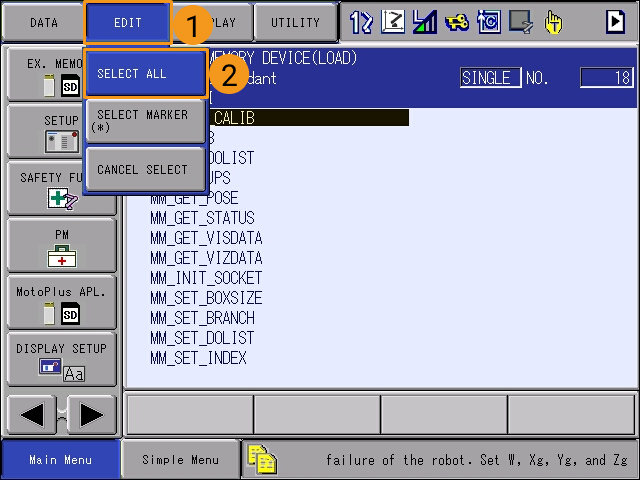
Select . Select JOB, and the programs to be loaded will be displayed.

-
Select .
-
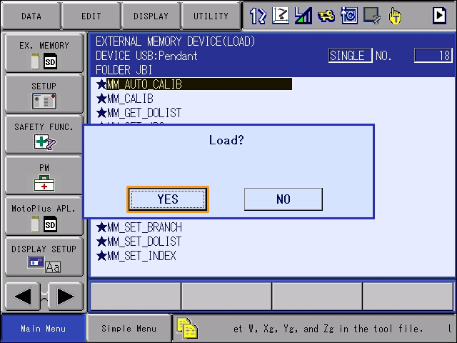
Press ENTER on the teach pendant. Select YES in the pop-up message to start loading the foreground programs.
If 4228 is displayed in the teach pendant interface, visit YRC1000 ALARM CODE 4228 WRONG DATA for troubleshooting.
-
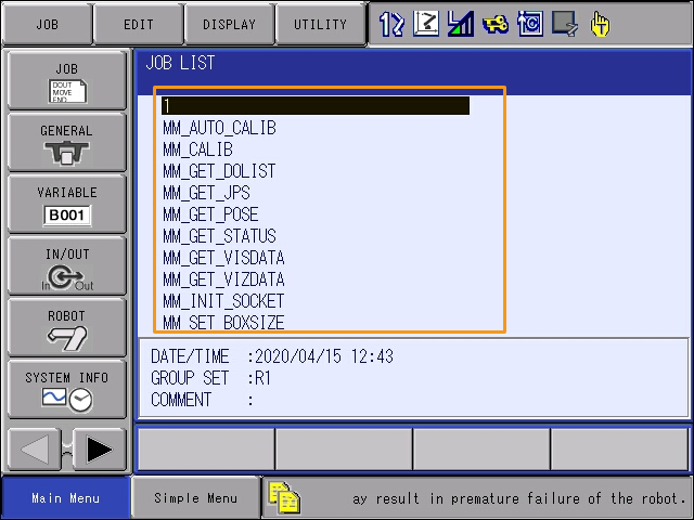
After loading the foreground programs, select to view the list of loaded programs. If you can see all foreground programs in the JOB LIST, the loading is successful.
Test Standard Interface Communication
-
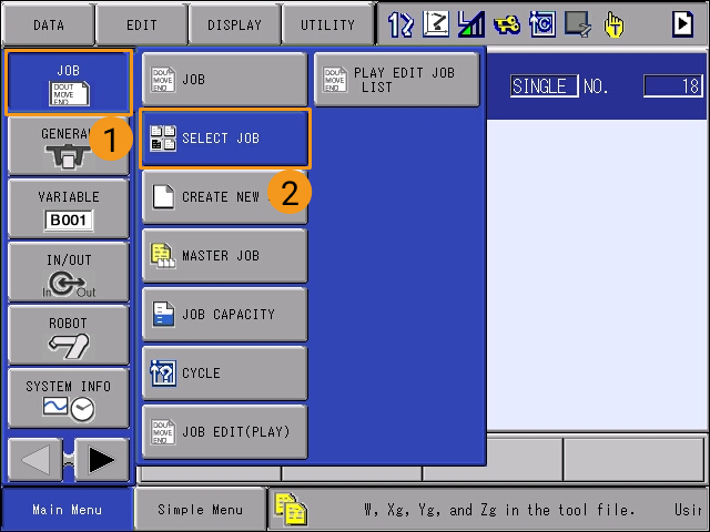
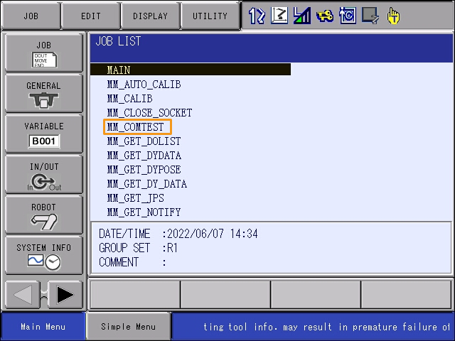
On the teach pendant, select on the Main Menu to enter the JOB LIST interface.
-
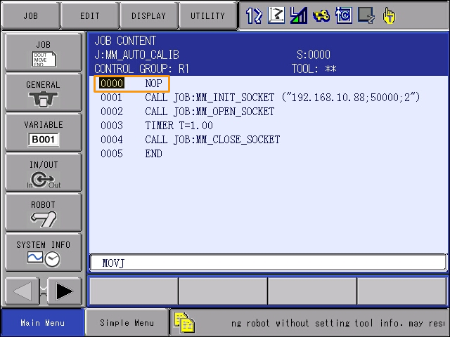
Select the MM_COMTEST program, and press SELECT to open the program.
-
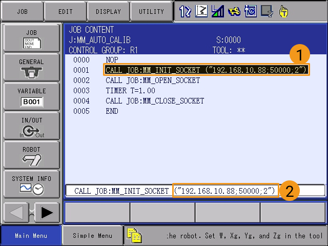
Select the content of line 0001, select the IP address and port number in the textbox at the bottom, and then press ENTER to enter the edit interface.
-
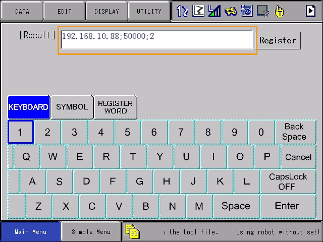
Change the IP address to that of the IPC. If the host port number set in Mech-Vision is modified, the port number 50000 here should be modified accordingly to make it consistent with the host port number set in Mech-Vision. After the modifications are completed, press the ENTER key at the bottom right of the teach pendant twice to return to the program content interface.
-
Turn the key of the teach pendant to the TEACH mode.
-
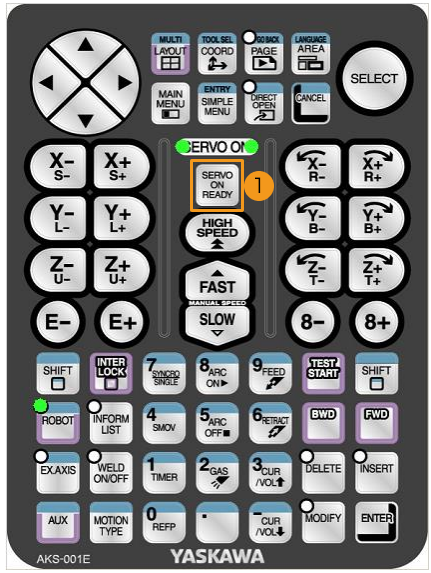
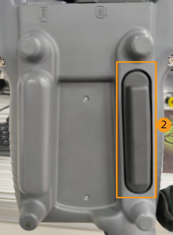
In the TEACH mode, press SERVO ON READY on the teach pendant, and then hold the deadman switch on the back while moving the cursor back to line 0000.
This step is to ensure that the job runs from the first line.
-
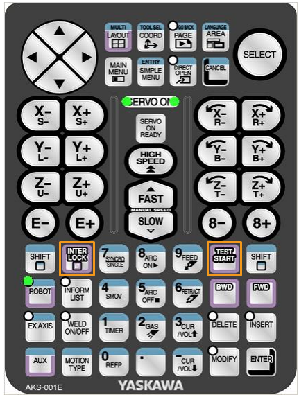
Press INTER LOCK and TEST START together on the teach pendant.
This step is a communication test.
-
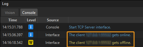
If the communication between the robot and the vision system is set up successfully, a log will be recorded in the Console tab of the log panel of Mech-Vision.
Appendix
Set IP Addresses
-
Press and hold MAIN MENU while starting the robot to enter the maintenance mode.
-
If you are not holding MAIN MENU when starting the robot, the system will enter the online mode.
-
If the robot is already started, please restart the robot while pressing MAIN MENU.
-
-
Select . Then select MANAGEMENT MODE.
-
Enter the password (which is sixteen 9s by default), and then select Enter to enter the MANAGEMENT MODE.
-
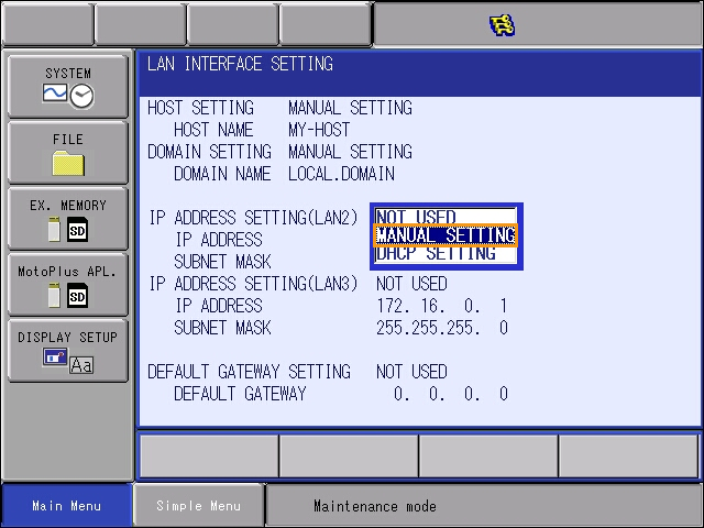
Select . At the OPTION FUNCTION interface, select LAN INTERFACE SETTING.
-
Set the IP address of LAN2: In the area of IP ADDRESS SETTING(LAN2), select MANUAL SETTING in the drop-down menu, and set proper values for IP ADDRESS and SUBNET MASK.
-
The IP address of LAN2 should be in the same subnet as that of the IPC.
-
The subnet mask should be 255.255.255.0.
-
-
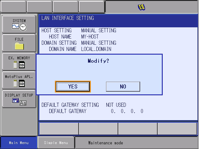
After modifying the IP address, press ENTER on the teach pendant, and a dialogue box saying Modify? will pop up. Select YES.