Example 6: MM_S6_Vis_Timer
Program Introduction
Description |
The PLC calculates the vision cycle time, which is the time it takes to trigger the Mech-Vision project to run and obtain the vision result. |
File path |
You can navigate to the installation directory of Mech-Vision and Mech-Viz and find the file by using the |
Project |
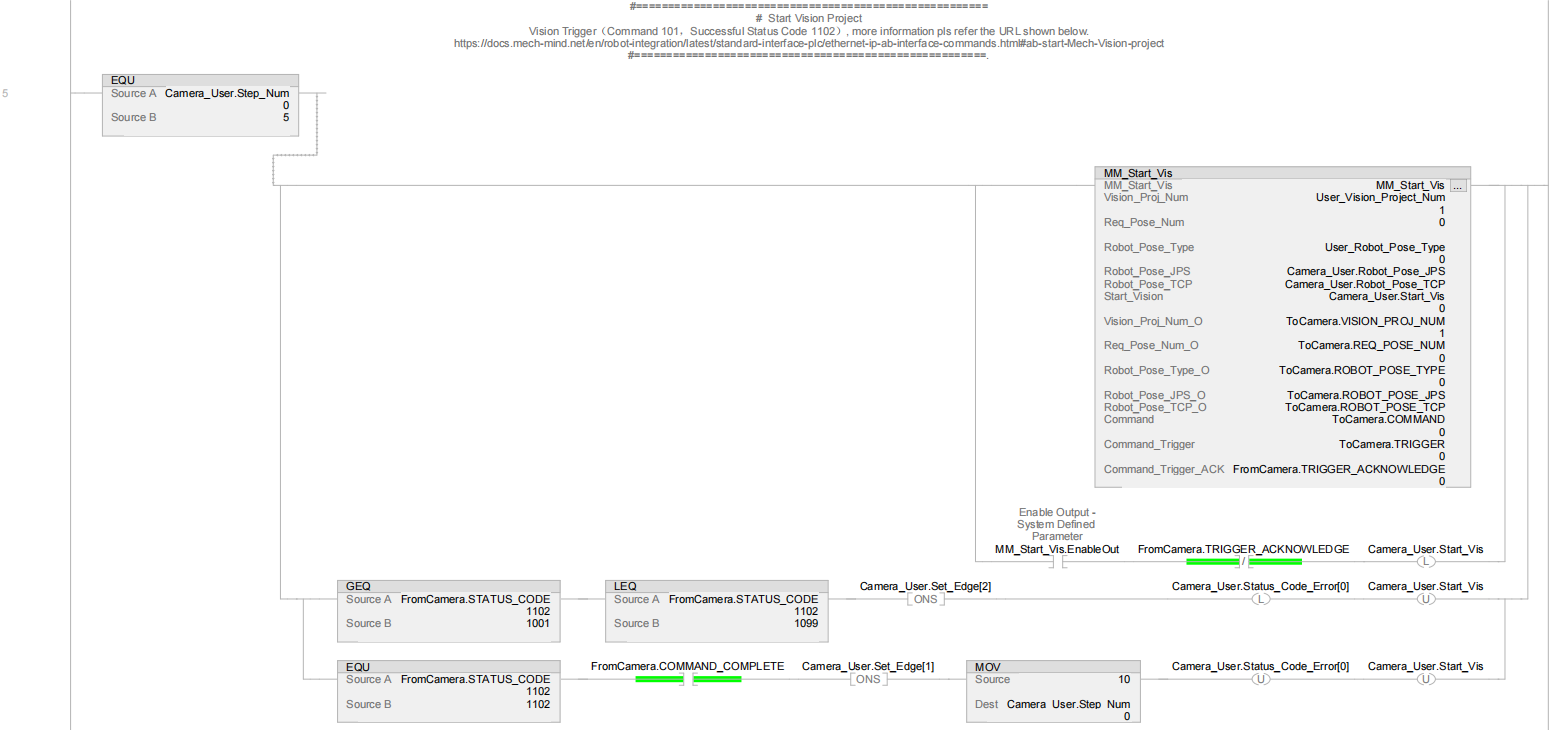
Mech-Vision project |
Prerequisites |
|
| This example program is provided for reference only. Before using the program, please modify the program according to the actual scenario. |
Program Description
This part describes the MM_S6_Vis_Timer example program.
| The only difference between the MM_S6_Vis_Timer example program and the MM_S1_Vis_Basic example program is that MM_S6_Vis_Timer can calculate the vision cycle time (Rung 7 to 9). As such, only the feature of switching the parameter recipe is described in the following section. For information about the parts of MM_S4_Vis_SwitchRecipe that are consistent with those of MM_S1_Vis_Basic, see Example Program 1: MM_S1_Vis_Basic. |
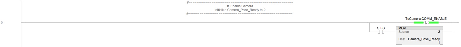


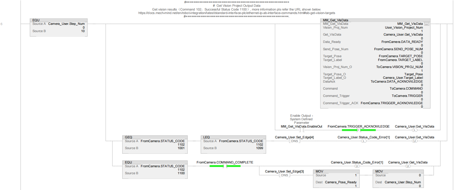


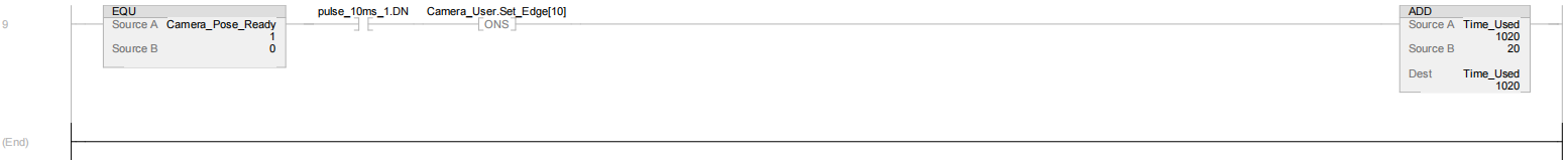
In the above example program, the feature of calculating the vision cycle time is shown in the figure below.
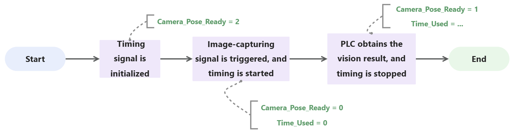
The table below illustrates the process of calculating the vision cycle time.
|
For common functions that come with AB PLC, please refer to Common Functions. |
| Feature | Description |
|---|---|
Calculate vision cycle time |
Rung 7 and 8 indicate that the delay timers (pulse_10ms_1 and pulse_10ms_2) are connected by using two TONs, and a 10 ms pulse width (pulse_10ms_1.DN) is generated. Therefore, the rising edge period of pulse_10ms_1.DN is 20 ms (10 × 2).
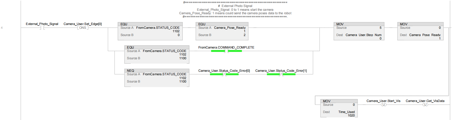
Rung 9: Calculate the amount of time (i.e. vision cycle time) for Camera_Pose_Ready to change from 0 (the external image-capturing signal has been triggered) to 1 (the PLC has obtained the vision result). The amount of time is calculated in 20 ms increments based on the Time_Used value. |