Set up Standard Interface Communication with FANUC
This guide shows how to load the Standard Interface program files to a FANUC robot, and set up the Standard Interface communication between Mech-Mind Vision System and the robot.
| In this section, you will load the robot Standard Interface program and the configuration files to the robot system to establish the Standard Interface communication between the vision system and the robot. |
Preparation
Check Controller and Software Compatibility
-
Ensure that the controller system software version is V7.5, V7.7, V8.x, or V9.x.
Click here for instructions
-
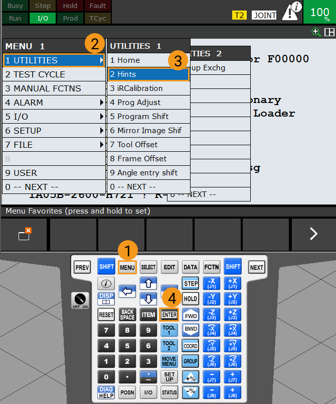
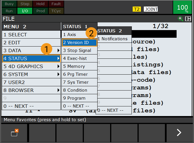
Press the MENU key on the teach pendant, select by using the arrow keys, and then press ENTER.
-
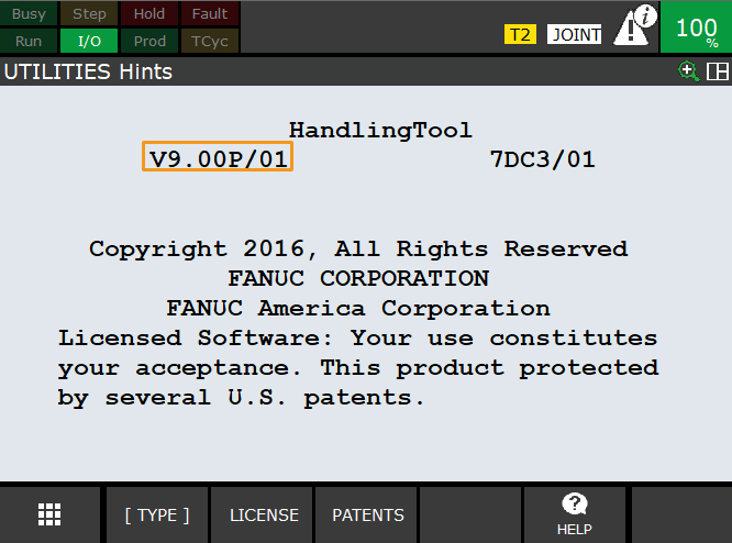
In the UTILITIES Hints interface, check the software version in the selected section.
-
-
Ensure that the required additional controller software packages are installed:
-
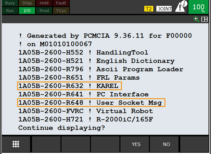
R651 or R632 (KAREL) MUST be installed.
-
R648 (User Socket Msg) MUST be installed.
Click here for instructions
-
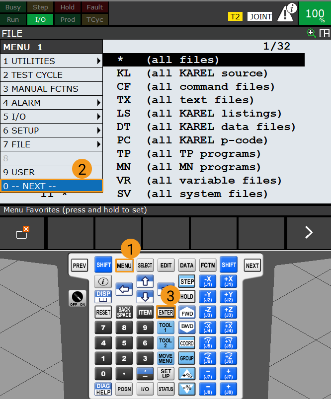
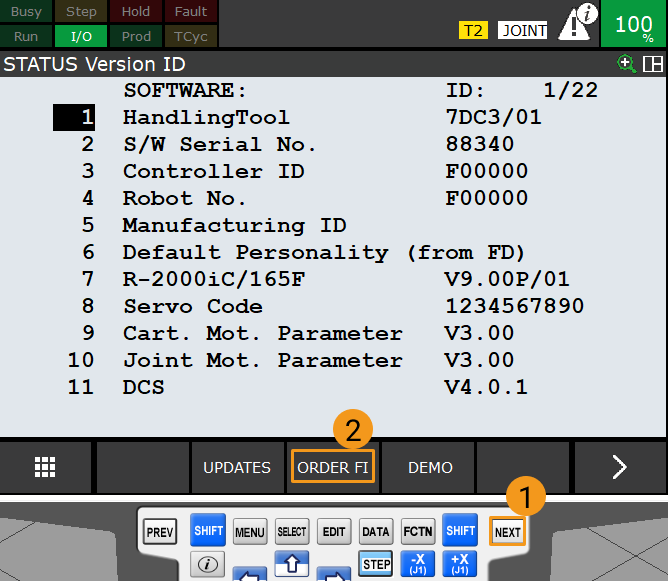
Press the MENU key on the teach pendant, select NEXT by using the arrow keys, and then press ENTER.
-
Select by using the arrow keys, and then press ENTER.
-
Press NEXT, and then press F3 (i.e., select ORDER FI).
-
Ensure that the required software packages are installed, as shown in the figure.
-
Set up the Network Connection
Connect the Hardware
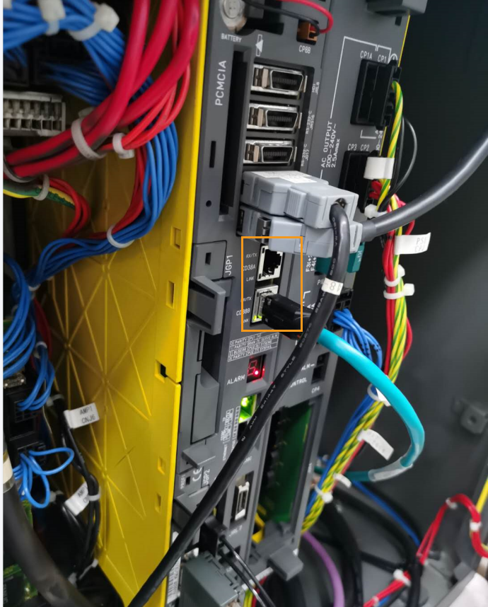
Connect one end of the Ethernet cable to the network port of the IPC and the other end to the CD38A or CD38B port of the robot controller’s motherboard, as shown in the figure below. CD38A corresponds to Port 1 in the robot IP setting, while CD38B corresponds to Port 2.
Set IP Addresses
-
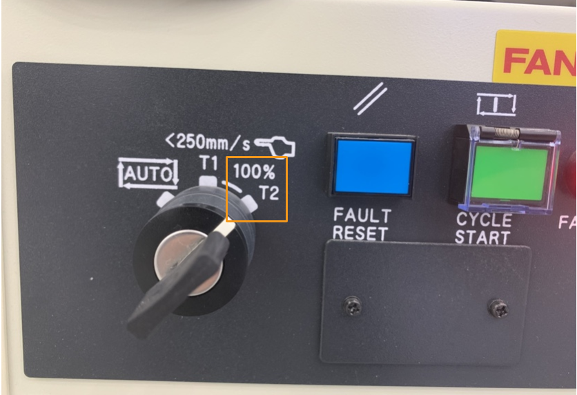
Switch the robot to the manual mode: Turn the switch of the teach pendant to ON, and turn the switch of the controller to T1 or T2.
T1 is the low-speed mode, and T2 is the high-speed mode. It is recommended that beginners use T1 mode. In this example, T2 is used. 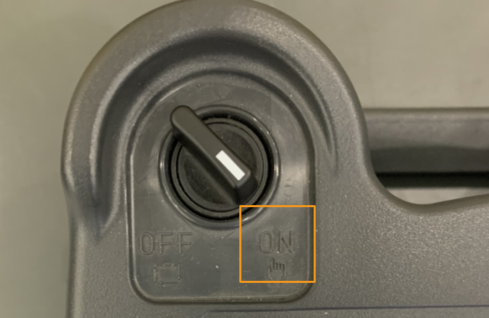
-
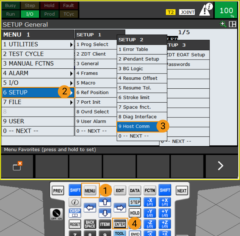
Press MENU on the teach pendant. Select by using the arrow keys. Press ENTER to open the SETUP Protocols interface.
-
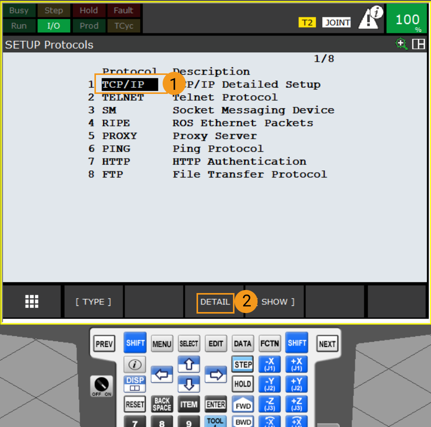
Select TCP/IP and press F3 (i.e., select DETAIL) to open the SETUP Host Comm interface.
-
Perform the corresponding operations based on the port to which the Ethernet cable is connected.
-
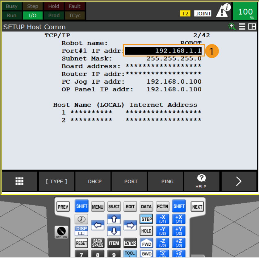
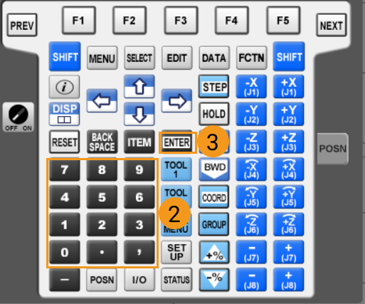
If the Ethernet cable is connected to the CD38A port (Port 1), select the IP address line by using the arrow keys, and press ENTER. Input the IP address by using the keyboard of the teach pendant, and press ENTER to finish. Note that the robot IP address should reside in the same subnet as that of the IPC, and the two IP addresses should be different.
-
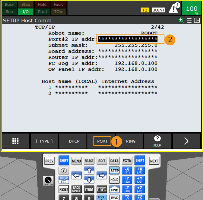
If the Ethernet cable is connected to the CD38B port (Port 2), press F3 (i.e. select PORT) to switch to Port 2. Select the IP address line by using the arrow keys, and press ENTER. Input the IP address using the keyboard of the teach pendant, and press ENTER to finish. Note that the robot IP address should reside in the same subnet as that of the IPC, and the two IP addresses should be different.
-
-
In the IPC, set the IP address of the IPC.
To allow communication between the IPC and the robot controller, the IP addresses of the IPC and robot controller must reside in the same subnet. This means that the network portions and subnet masks of the IP addresses should be the same. For example, 192.168.100.169/255.255.255.0 and 192.168.100.170/255.255.255.0 are in the same subnet.
Set up Robot Communication Configuration
-
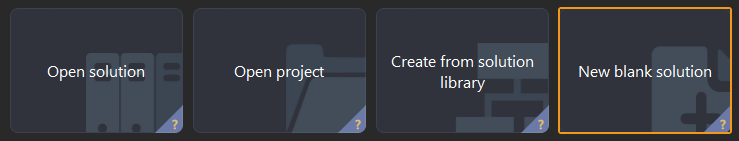
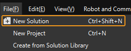
Open Mech-Vision, and you may enter different interfaces. Create a new solution according to the instructions below.
-
If you have entered the Welcome interface, click New blank solution.
-
If you have entered the main interface, click on the menu bar.
-
-
Click Robot Communication Configuration on the toolbar of Mech-Vision.
-
In the Robot Communication Configuration window, complete the following configurations.
-
Click the Select robot drop-down menu, and select Listed robot. Click Select robot model, and select the robot model that you use. Then, click Next.
-
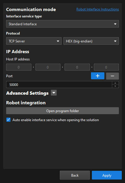
In the Communication mode section, select Standard Interface for Interface service type, TCP Server for Protocol, and HEX (big-endian) for the protocol format.
-
It is recommended to set the port number to 50000 or above. Ensure that the port number is not occupied by another program.
-
(Optional) Select Auto enable interface service when opening the solution.
-
Click Apply.
-
-
On the main interface of Mech-Vision, make sure that the Robot Communication Configuration switch on the toolbar is flipped and has turned blue.

Back up Robot Programs
-
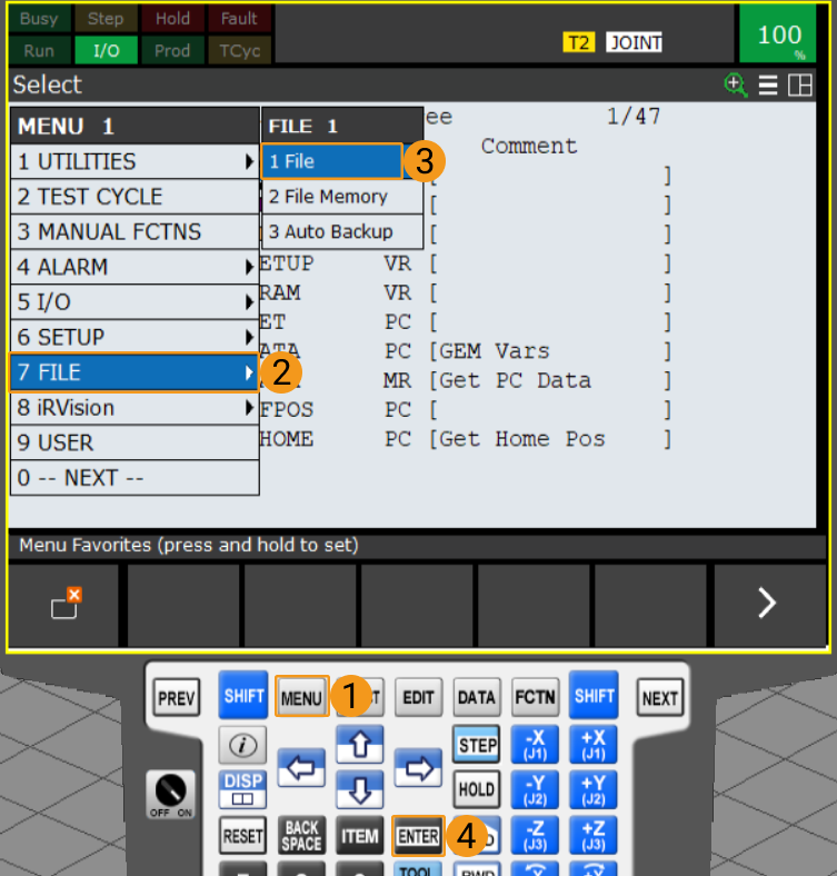
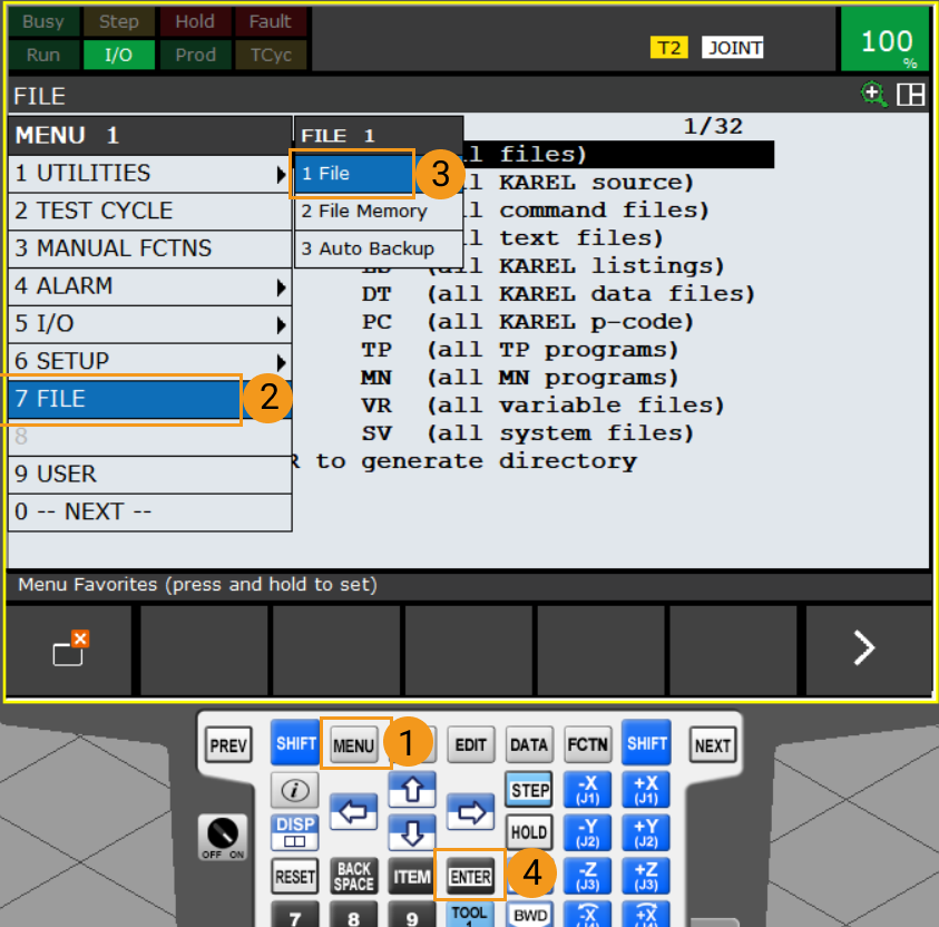
Insert the flash drive, and press MENU. Select by using the arrow keys. Then, press ENTER to open the FILE interface.
-
Please ensure that your flash drive is no more than 32 GB in size and that the file system of the flash drive is FAT32.
-
You can connect the flash drive to the robot controller or the teach pendant based on the actual requirement.
-
-
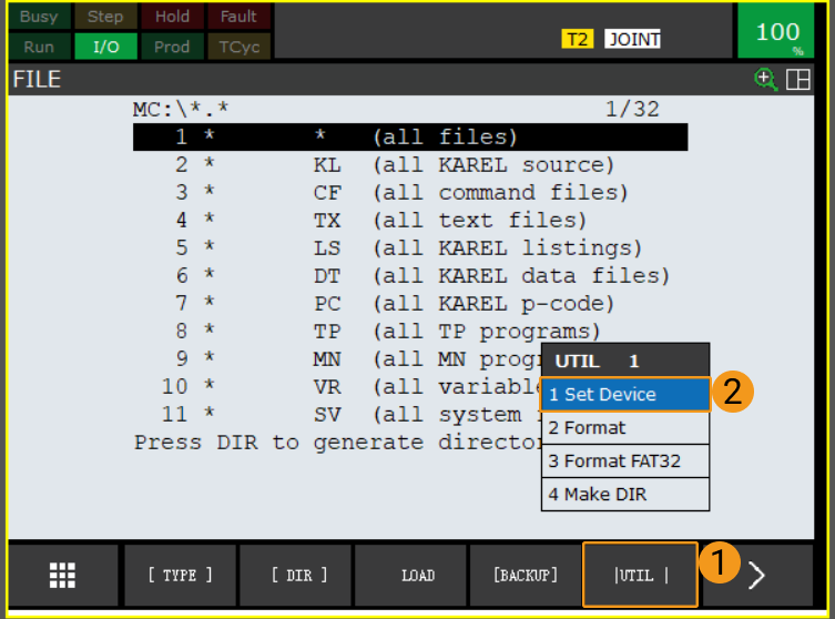
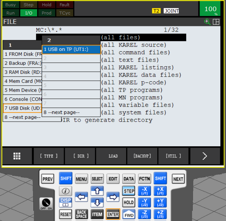
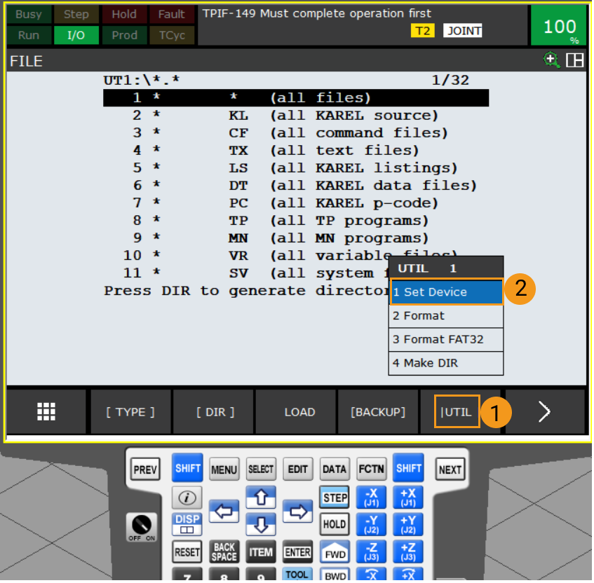
In the FILE interface, press F5 (i.e., select UTIL). Select Set Device by using the arrow keys, and press ENTER.
-
Perform the corresponding operations based on the device to which the flash drive is connected.
-
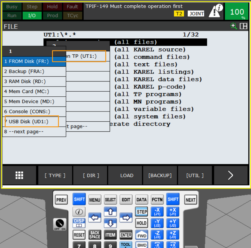
If your flash drive is connected to the controller, select USB Disk (UD1:) by using the arrow keys, and press ENTER.
-
If your flash drive is connected to the teach pendant, select USB on TP (UT1:) by using the arrow keys, and press ENTER.
-
-
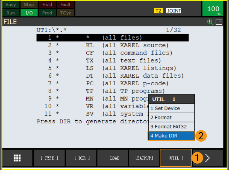
In the FILE interface, press F5 (i.e., select UTIL). Select Make DIR by using the arrow keys, and press ENTER.
-
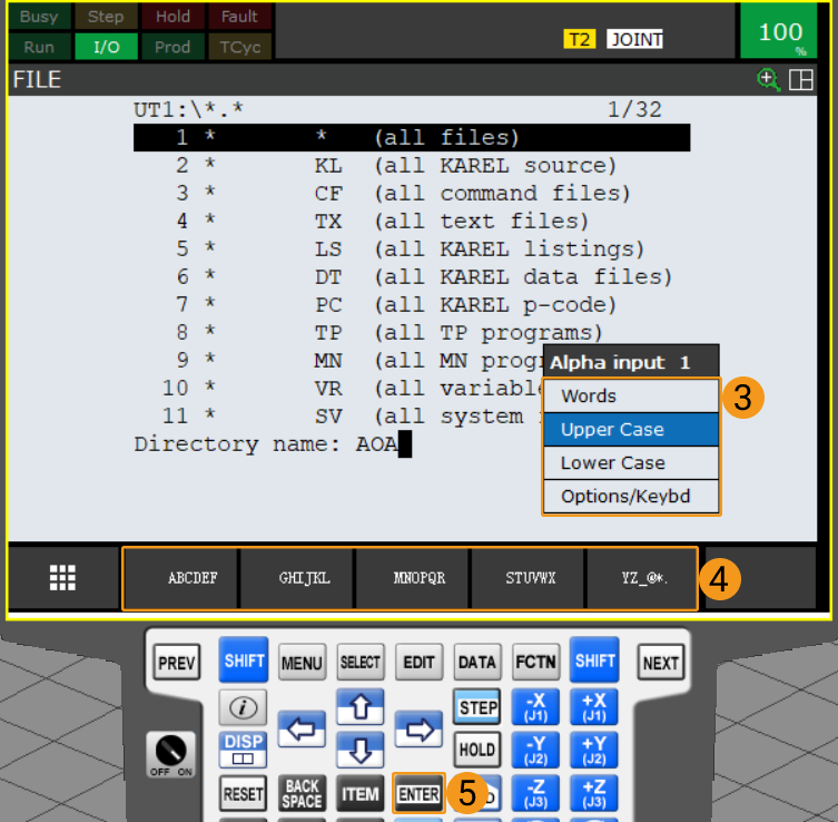
Select Words, Upper Case, Lower Case, or Options/Keybd and use the keys F1~F5 to name the folder, for example, as AOA. Then, press ENTER to confirm and enter the new folder.
-
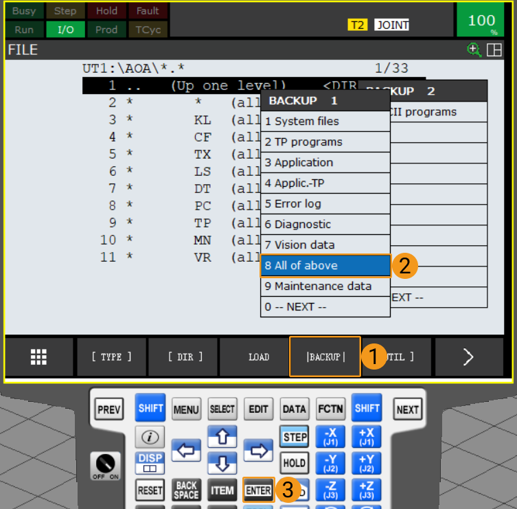
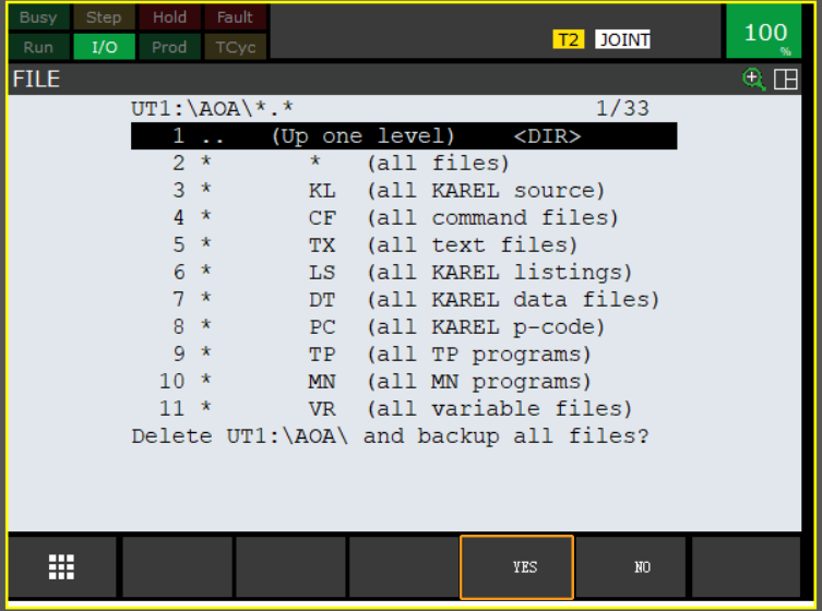
Press F4 (i.e., select BACKUP). Select All of above by using the arrow keys, and press ENTER to back up the files.
-
A message asking whether to delete the new folder before backing up files will be displayed on the screen. Press F4 to select YES. Then, a message asking whether to back up all files will be displayed on the screen. Press F4 to select YES.

-
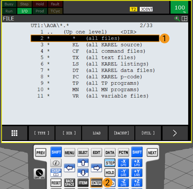
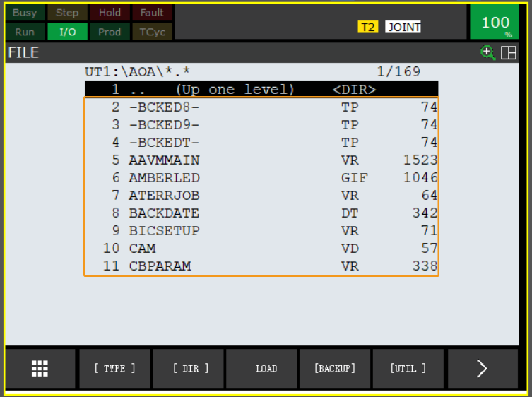
After the backup is complete, select all files by using the arrow keys, and then press ENTER to view all backup files.
Prepare Program Files
Navigate to Communication Component/Robot_Interface from the installation directory where Mech-Vision and Mech-Viz are installed. Copy all contents of the FANUC folder to the root directory of your flash drive.
|
Load the Program Files
-
Insert the flash drive, and press MENU. Select by using the arrow keys. Then, press ENTER to open the FILE interface.
You can connect the flash drive to the robot controller or the teach pendant based on the actual requirement.
-
Press F5 (i.e., select UTIL). Select Set Device by using the arrow keys, and press ENTER.
-
Perform the corresponding operations based on the device to which the flash drive is connected.
-
If your flash drive is connected to the controller, select USB Disk (UD1:) by using the arrow keys, and press ENTER.
-
If your flash drive is connected to the teach pendant, select USB on TP (UT1:) by using the arrow keys, and press ENTER.
-
-
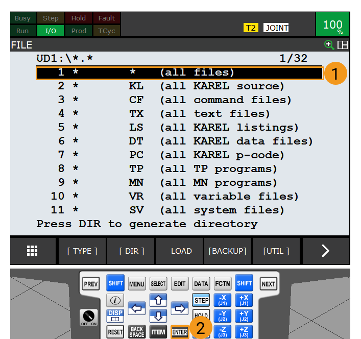
Select all files by using the arrow keys, and press ENTER to view the root directory of the flash drive.
-
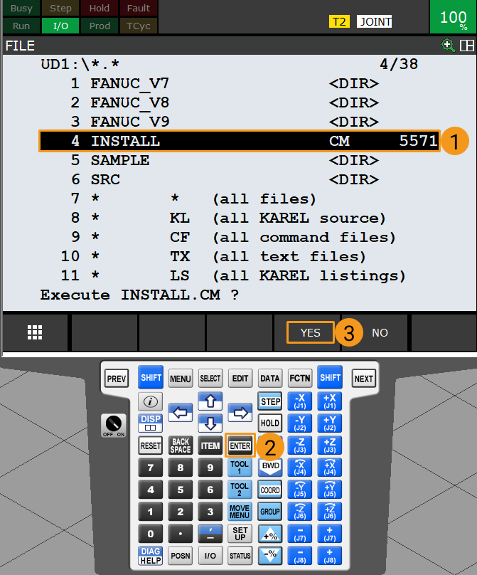
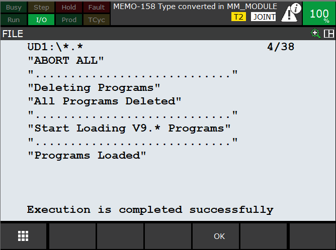
In the root directory of the flash drive, select INSTALL by using the arrow keys. Press ENTER, and press F4 (i.e., select YES) to start loading the programs.
-
When the message “Programs Loaded” is displayed, the program files have been loaded successfully. Press F4 (i.e., select OK) to return to the previous interface.
Test Standard Interface Communication
Select and Modify the Program Used for the Communication Test
-
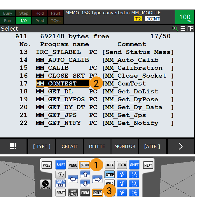
After you load the program files, press SELECT on the teach pendant to enter the program selection interface. Select MM_COMTEST by using the arrow keys and then press ENTER to start the program.
-
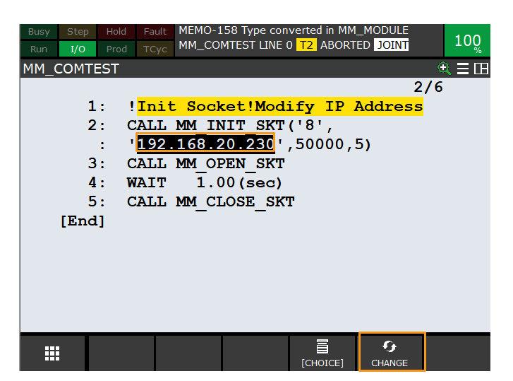
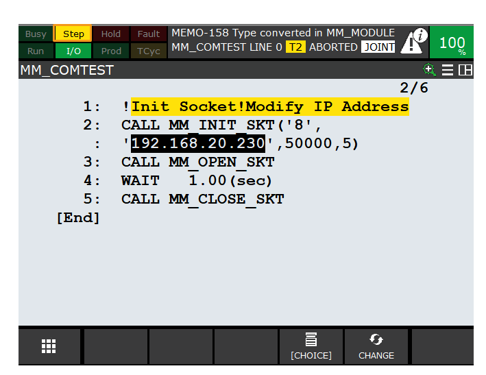
In the MM_COMTEST interface, set the MM_COMTEST function. This function has four parameters. Select one of the parameters by using the arrow keys, press F5 to select CHANGE, and then change the value as needed.
-
Parameter 1: Robot port number. Please select a robot port from ports 1 to 8.
-
Parameter 2: IP address of the IPC
-
Parameter 3: IPC (server) port number, which should be the same as the setting in Mech-Vision
-
Parameter 4: timeout period (min)
-
Run the Program and Test Connection
-
Switch the robot to the manual mode: Turn the switch of the teach pendant to ON, and turn the switch of the controller to T1 or T2.
-
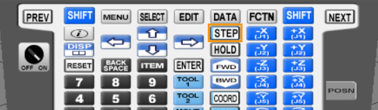
Press STEP on the teach pendant to switch to Step mode. Now the Step icon on the teach pendant turns yellow as shown below.
-
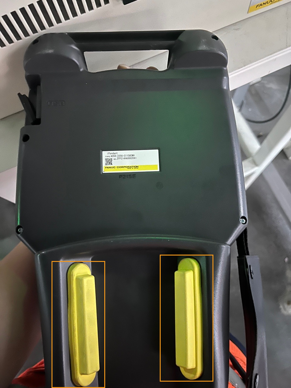
Press and hold one of the enabling switches on the back of the teach pendant.
-
Press and hold SHIFT, and then repeatedly press FWD to manually run the MM_COMTEST program in Step mode. If the MM:Restart Robot information is returned, restart the robot.
After the robot port number (1 to 8) is modified for the first time, the changes will only take effect after the robot restarts. 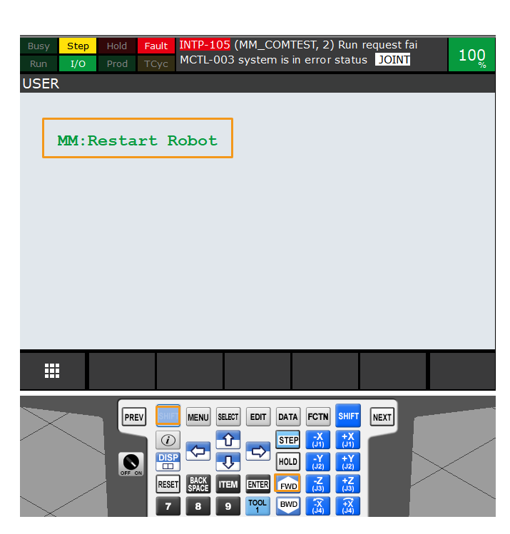
-
After you restart the robot, re-select and open the MM_COMTEST program, press and hold SHIFT, and then repeatedly press FWD to manually run MM_COMTEST in Step mode.
-
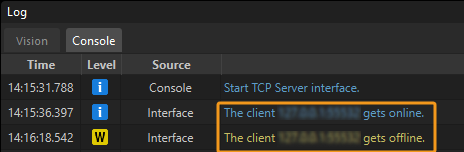
If the communication between the robot and the vision system is set up, a log will be recorded on the Console tab of the log panel of Mech-Vision.