Manual Hand-Eye Re-Calibration in the Eye-to-Eye Setup
This how-to guide introduces how to complete the manual hand-eye re-calibration in the eye-to-eye (ETE) setup.
Preparation before Calibration
Before hand-eye calibration, you need to finish the following preparations:
Construct the Vision System
Construct the Mech-Mind Vision System by referring to the section Vision System Hardware Setup.
You need to use Mech-Eye Viewer, Mech-Vision and Mech-Viz during hand-eye calibration. Please ensure that they have been installed and are running the latest versions.
Prepare the Materials Required for Calibration
The hand-eye calibration in the ETE setup needs to use the calibration board. Please prepare the calibration board according to the following requirements:
-
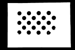
Ensure that the circles of the calibration board are clearly visible and without obvious scratches, and the board does not suffer from deformations.
-
In the ETE setup, mount the robot-specific bracket for calibration board onto the robot flange, and then mount the calibration board onto the bracket. Ensure that the calibration board is securely mounted, located at the center of the camera’s field of view, and as parallel to the plane where the camera is located as possible.
If an undetachable gripper is connected to the robot flange, you can attach the calibration board directly to the gripper.
In addition, before calibration, move the robot to the starting point for calibration, that is, the bottom middle of the overlapped area of the two cameras’ field of view.
Check the Point Cloud Quality of the Calibration Board
| The point cloud quality of the calibration board will affect the accuracy of hand-eye calibration. Check the point cloud quality of the calibration board to ensure the accuracy and reliability of the calibration results. The calibration process includes the step of checking the point cloud quality of the calibration board. You can also check the point cloud quality of the calibration board before starting the calibration to save time. |
-
Place the calibration board horizontally at the center of the working plane within the camera’s field of view.
-
Open the Mech-Eye Viewer software, select the camera used by the project, and then select the “calib” parameter group and adjust camera parameters.
-
Adjust the 2D parameters to ensure that the overall 2D image is not too dark, and each calibration circle is clearly visible.
-
Adjust the 3D parameters to ensure that each calibration circle on the calibration board is complete and visible.
If the on-site ambient lights are not ideal and affect the quality of 2D images and point clouds, you can use shading or supplemental light to improve the lighting conditions.
-
Make sure that the point cloud quality of the calibration board is up to standard after completing the preceding steps.
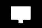
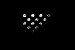
Normal Overexposed Underexposed 2D image
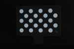
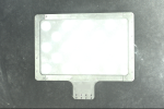

Point cloud
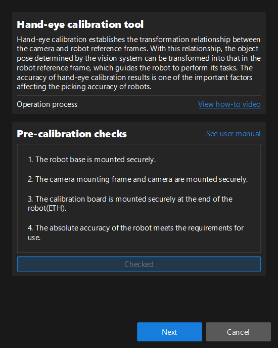
Complete Pre-calibration Checks
Please refer to Pre-calibration Checks and complete the following checks:
-
Confirm that the robot base is mounted securely.
-
Confirm that the camera mounting frame and camera are mounted securely.
-
Confirm that the absolute accuracy of the robot meets the requirements for use.
-
Verify robot model parameters.
-
Confirm that the camera is warmed up.
Pre-calibration Configuration
-
Open Mech-Vision, select a project in the project list, and then click the Camera Calibration button in the toolbar. The Configuration before Calibration window will be prompted.
-
After confirming that pre-calibration checks are completed, click I’ve finished all checks, and then click Next.
-
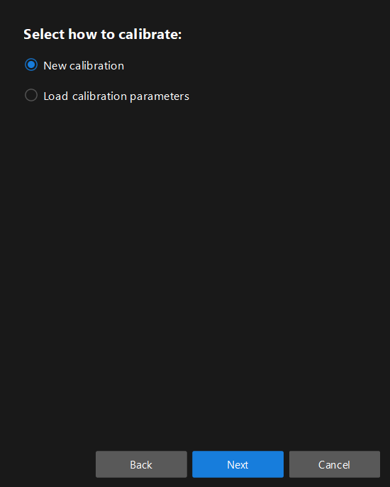
In the Select how to calibrate window, select the New calibration radio button, and then click the Next button.
-
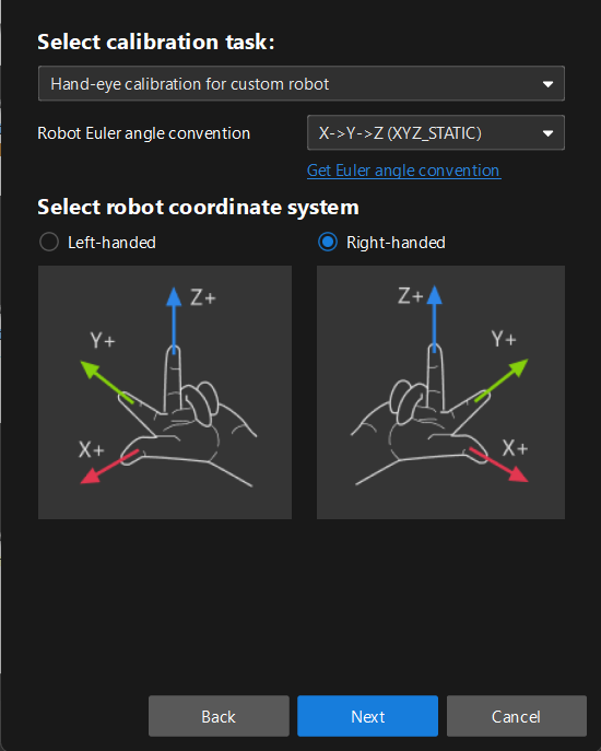
In the Select calibration task window, select Hand-eye calibration for custom robot from the drop-down list box, select the robot Euler angle convention, select the robot coordinate system, and then click the Next button.
-
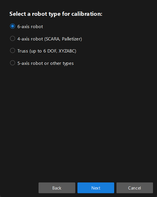
In Select a robot type for calibration window, select a robot type among 6-axis robot, 4-axis robot (SCARA, Palletizer) or 5-axis robot or other types radio button, and then click the Next button.
-
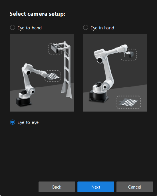
In the Select camera setup window, select the Eye to eye radio button.
-
In the Select how to collect data window, select Multiple random calibration board poses, and then click the Calibrate button. The Calibration (Eye to Eye) window will be prompted.
Till now, you have completed the pre-calibration configuration and can start the calibration procedure.
Perform Calibration
Connect to Camera
-
In the Connect to camera step, select the sub-camera to connect in the Detected cameras list, and then click the
 button or double-click the camera entry to connect to it.
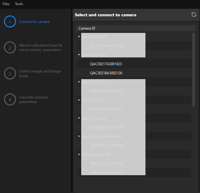
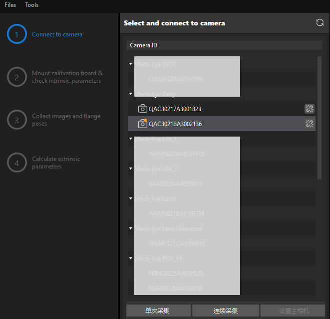
-
Repeat the preceding step to connect to the primary camera. After the primary camera is connected, the
 icon will be displayed before the camera ID.
To switch the primary camera, select a camera, and then click the Set as main button.
-
After the camera is connected, click the Capture live or Capture once button.
-
In the Image viewer panel, ensure that the camera can capture images normally and click the Next button on the bottom bar.
In this step, the 2D image and depth map are captured only for the primary camera. To confirm the effects of the images captured by the secondary camera, you can switch it to the primary camera, and switch the original primary camera back to the primary camera after confirming.
Mount Calibration Board & Check Intrinsic Parameters
-
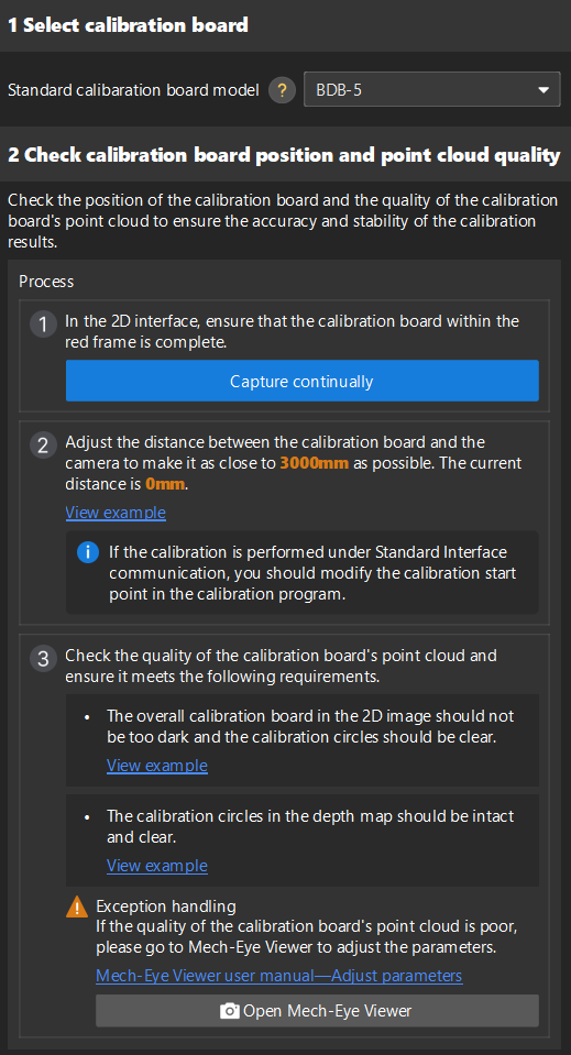
In the Mount calibration board & check intrinsic parameters step, set the Standard calibration board model parameter in the 1 Select calibration board area.
-
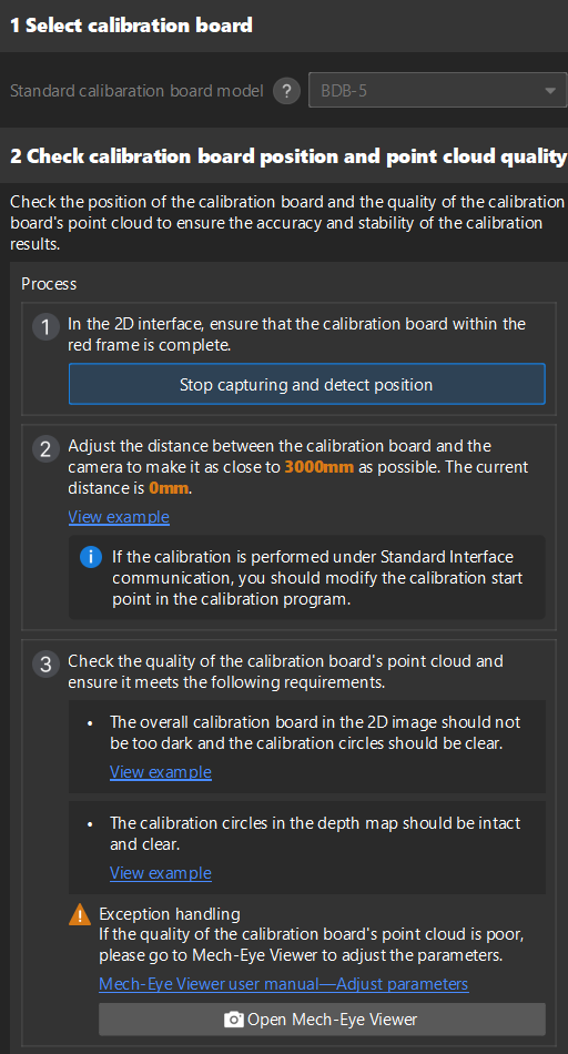
In the 2 Check calibration board position and point cloud quality area, read carefully the requirements on the calibration board position and point cloud quality, and then click the Capture continually button. The Capture continually button will turn into Stop capturing and detect position.
-
Manually control the robot carrying the calibration board to move to an appropriate position, ensuring the calibration board is fully within the red frame, and the distance between the calibration board and the camera is as close to the recommended value on the interface as possible.
If the Standard Interface communication mode is used for calibration, after adjusting the distance between the calibration board and the camera according to the prompts on the interface, the robot’s position can be used as the starting point for calibration. -
Please ensure that the 2D image and depth map of the calibration board meet the requirements, and then click the Stop capturing and detect position button.
If the captured images do not meet the requirements, click Open Mech-Eye Viewer button to open the Mech-Eye Viewer software, adjust the 2D and 3D exposure parameters and re-capture images. Please note that you need to change the Parameter group parameter to “calib” first.
-
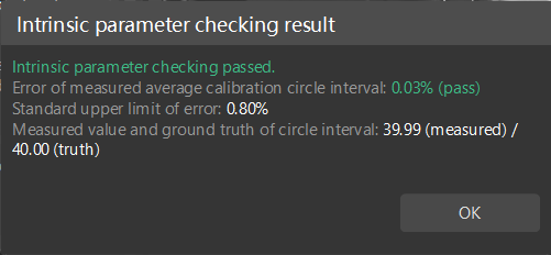
In the 3 Check intrinsic parameters area, click the Check intrinsic parameters button.
-
Confirm the results of the camera intrinsic parameter check.
-
If the camera intrinsic parameter check passes, click the OK button in the prompted window, and then click the Next button on the bottom bar.
-
If the intrinsic parameter check fails, you can draw aid circles to assist in the intrinsic parameter check, and then click the Recheck intrinsic parameters button.
-
Draw Aid Circle
-
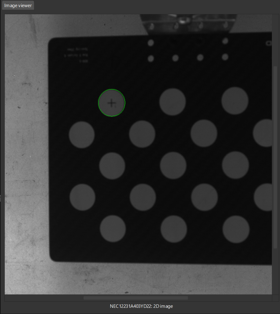
To draw an aid circle, click the Draw an aid circle button.
-
In the right Image viewer panel, right-click the calibration board image, clear the Fit to window checkbox, press the Ctrl key and drag the roller to adjust the image to a suitable size.
-
Move the mouse pointer to the cross center point of the calibration circle, press the left mouse button and make the aid circle completely include the calibration circle and then release the left mouse button.
-
Click the Recheck intrinsic parameters button, and confirm that the camera intrinsic parameter check passes. If the intrinsic parameter check still fails, please contact Technical Support.
Obtain Images and Poses
-
In the Obtain Images and Poses step, control the robot to move to different calibration points and then click the Add images and record flange poses button.
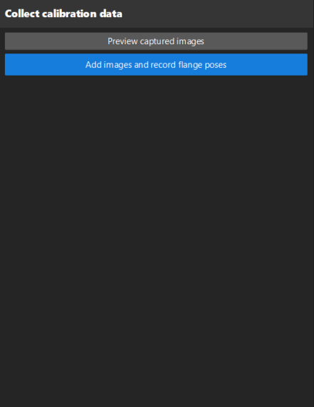
After moving the robot to different calibration points, please record the pose of each point in the robot program for easy retrieval during re-calibration. -
In the prompted window, enter the robot flange pose.
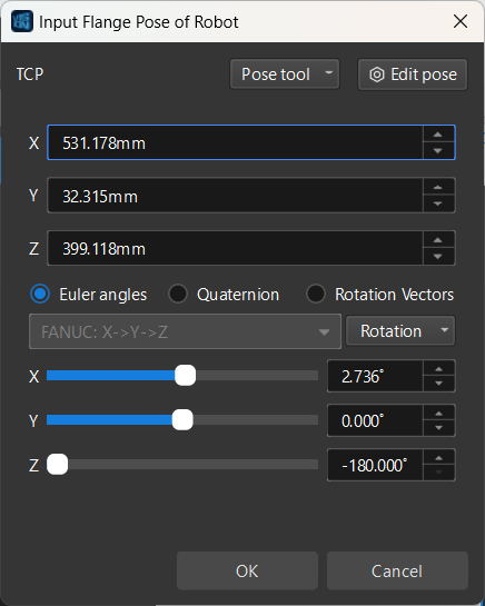
Please create a new local file (.txt or .xlsx) to save the input robot flange poses for easy input during re-calibration. -
Repeat the above steps until the added calibration points meet the data requirements. Then click the Next button on the bottom bar.
Calculate Extrinsic Parameters
-
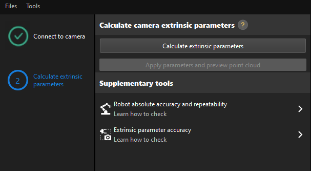
In the Calculate extrinsic parameters step, click the Calculate extrinsic parameters button in the 1 Calculate extrinsic parameters and check results area.
-
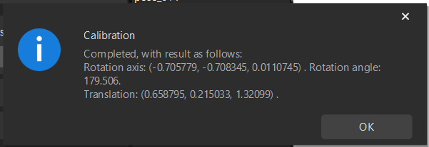
In the prompted window indicating calibration success, click the OK button.
-
Click the Save button on the bottom bar. In the prompted Save Calibration Files dialog box, click the OK button. The camera calibration result will be automatically saved in the “calibration” directory of the project.
|
Till now, the calibration process is completed.
Perform ETE calibration by loading existing calibration parameters
-
Open Mech-Vision, and click the Camera Calibration button in the toolbar. The Configuration before Calibration window will be prompted.
-
After confirming that pre-calibration checks are completed, click I’ve finished all checks, and then click Next.
-
In the Select how to calibrate window, select the New calibration radio button, and then click the Next button.
-
In the Select calibration task window, select Hand-eye calibration for custom robot from the drop-down list box, specify the Robot Euler angle convention parameter, select the robot coordinate system type, and then click the Next button.
-
In Select a robot type for calibration window, select a robot type among 6-axis robot, 4-axis robot (SCARA, Palletizer) or 5-axis robot or other types radio button, and then click the Next button.
-
In the Select camera setup window, select the Eye to eye radio button, and then click the Next button.
-
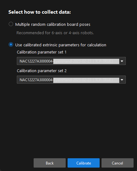
In the Select how to collect data window, select the Use calibrated extrinsic parameters for calculation, choose two camera’s extrinsic parameter files, and then click the Calibrate button. The Calibration (Eye to Eye) window will be prompted.
-
In the Connect to camera step, select the camera to connect in the Camera ID list, and then click the
button to connect to it. -
Repeat the preceding step to connect to the second camera, and then click the Next button on the bottom bar.
-
In the Calculate extrinsic parameters step, click the Calculate extrinsic parameters button.
After the camera extrinsic parameters have been calculated, you can view the fused point cloud in the Point cloud viewer panel.
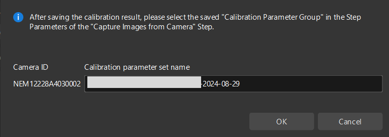
Apply Calibration Result
The calibration parameter group includes the intrinsic parameter and extrinsic parameter files of the camera. If you have used the camera’s calibration parameter group in the Mech-Vision project, you need to select the new calibration parameter group in the Mech-Vision project after hand-eye calibration.
-
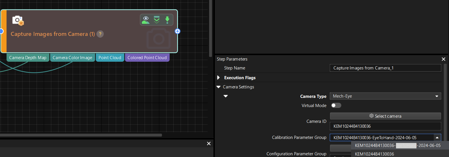
Select the Capture Images from Camera Step.
-
In the Step Parameters panel, click
 of the Calibration Parameter Group parameter, and select the new calibration parameter group.
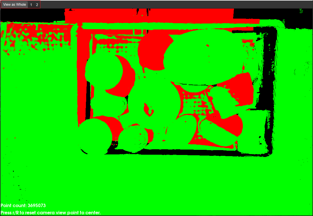
Check the Fusion Effect of the Calibration in the ETE Setup Using a Mech-Vision Project
You can build a project as shown in the following figure. Note that the "Trigger Control Flow Given No Output" and "Trigger Control Flow Given Output" options in Execution Flags area should be selected.
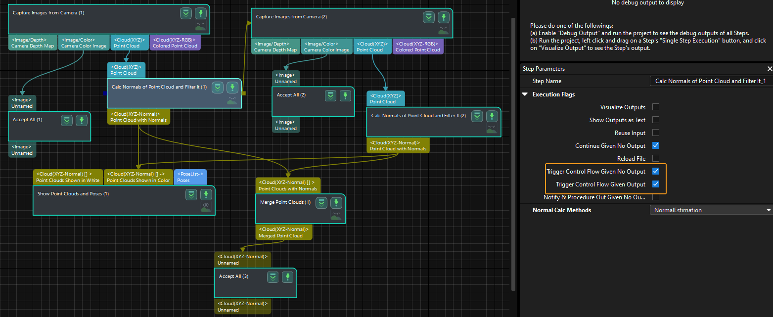
Execute the single Step “Merge Point Clouds” to display the fused point cloud. The point cloud output after merging is the fused whole point cloud, as shown in the figure below. You can click the upper left corner View as Whole| 1 | 2 to switch point clouds.