3D Simulation Area
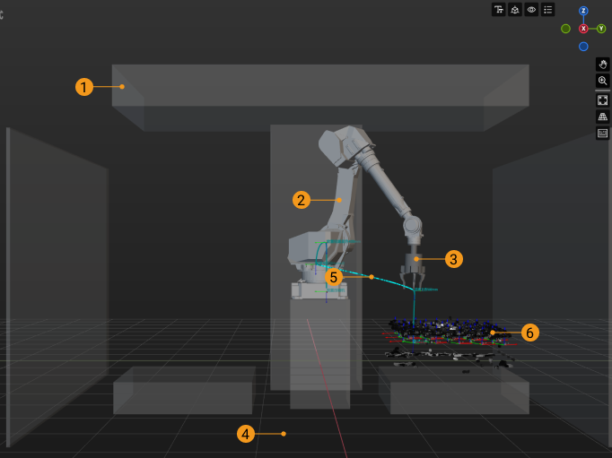
The robot, scene objects, tools, target object models, robot motion path, pick points, and collisions will be displayed in the 3D simulation area. You can also drag to move the models of scene objects in this area.

No. |
Description |
1 |
Scene objects |
2 |
Robot |
3 |
Tools |
4 |
Floor |
5 |
Planned path |
The 3D simulation area can display the motion path of both the real robot in actual application and the simulated robot in project simulation.
|
|
6 |
Vision result |
The vision result returned by the vision service will be displayed in the 3D simulation area.
|

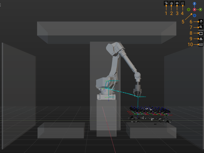
No. |
Description |
1 |
Click this icon to view the menu showing the font size and axis size. |
2 |
Click this icon to view the menu showing the visibility of reference frames. |
3 |
Click this icon to view the menu showing the visibility of the components in the vision results. |
4 |
Click this icon to view the menu showing the color legend of vision poses. |
5 |
The navigation gizmo shows the current view in the workspace. |
Click the icon of each axis (X, Y, Z, -X, -Y, -Z) to align the view with the axis. Press and hold the left mouse button and drag the navigation gizmo to rotate the view. |
|
6 |
Pan the view |
Press and hold this icon (or Shift + Scroll wheel), and then drag the icon to pan the view. |
|
7 |
Zoom in/out |
Press and hold this icon, and then drag it upward (or scroll the mouse forward) to zoom in, or drag it downward (or scroll the mouse downward) to zoom out. |
|
8 |
Fit the view |
9 |
Click this icon to switch to perspective/orthographic view. |
10 |
Show pressed keyboard keys and mouse buttons |
Once this icon is selected (highlighted in blue), the keyboard keys and mouse buttons you pressed will be displayed in the lower right corner in the 3D simulation area. |