Update Scene Objects
Function
Update the pose and dimensions of the specified scene object via the vision service or parameter settings.
Usage Scenario
Suitable for scenarios where the pose and dimensions of the scene object model need to be updated while Mech-Viz running to avoid collisions.
Parameter Description
Update Info Source
This parameter specifies the information source to update the scene object’s pose and dimensions. There are two Update Info Sources, i.e., Specified value and Vision service.
Config Value
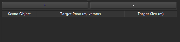
+: Add an scene object to be updated in the list.
-: Delete the selected scene object in the list.
Please add or delete the scene object as needed. When executed, the software will process sequentially from top to bottom.
After adding scene objects, select the scene object to be updated from the dropdown list and set its target pose and target size. The target pose includes X/Y/Z coordinates (unit: meters) and quaternions, totaling 7 values. The target size contains X/Y/Z dimensional information (unit: meters).
For example, a target pose can be 1.00, 0.00, 0.00, 1.00, 0.00, 0.00, 0.00, a target size of a cuboid can be 0.40, 0.40, 1.00 (length, width, height), and a target size of a vertical cylinder can be 0.50, 1.00, 0.00 (radius, height, 0).
Vision Service
| When Vision Service is used to update the scene objects, ensure that a Visual Recognition Step has been added in the preceding workflow. |
Vision Service Name
Select the name of the Mech-Vision project that provides the vision service.
-
When the Port Type of the “Output” Step in the Mech-Vision project is set to Predefined (vision result), please follow the steps below to configure the Step:
-
Select the Update Scene Object parameter under Update Scene Object Settings.
-
Connect the new input ports of the “Output” Step with corresponding output ports respectively.
-
-
When the Port Type of the “Output” Step in the Mech-Vision project is set to Custom, please follow the steps below to configure the Step:
-
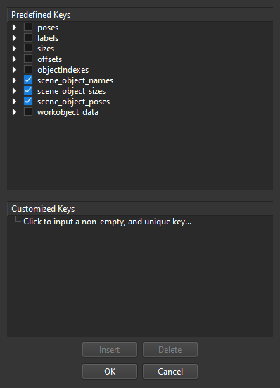
Click Open the editor to open the Output Setting Assistant.
-
Select scene_object_names, scene_object_sizes, and scene_object_poses under Predefined Keys.
-
Click OK to save the changes.
-
Connect the new input ports of the “Output” Step with corresponding output ports respectively.
-
| Customized Keys | Description |
|---|---|
scene_object_names |
The name should be consistent with that of the scene object to be updated in Mech-Viz. |
scene_object_sizes |
X/Y/Z dimensional information (unit: meters). For cuboids, the three values represent length, width, and height, respectively. For cylinders, the three values represent radius, height, and a null value, respectively. |
scene_object_poses |
X/Y/Z coordinates (unit: meters) and quaternions, totaling 7 values. |