Robot Communication Configuration
In this tutorial, you will learn how to load the Standard Interface program files to the KUKA robot, and set up the Standard Interface communication between the Mech-Mind Vision System and the robot.
|
Preparation before Loading
Check Controller and Software Compatibility
-
The robot was identified as a KUKA 6-axis robot. This section takes KUKA_KR_10_R1100_2_HO as an example.
-
The controller version is KR C4.
-
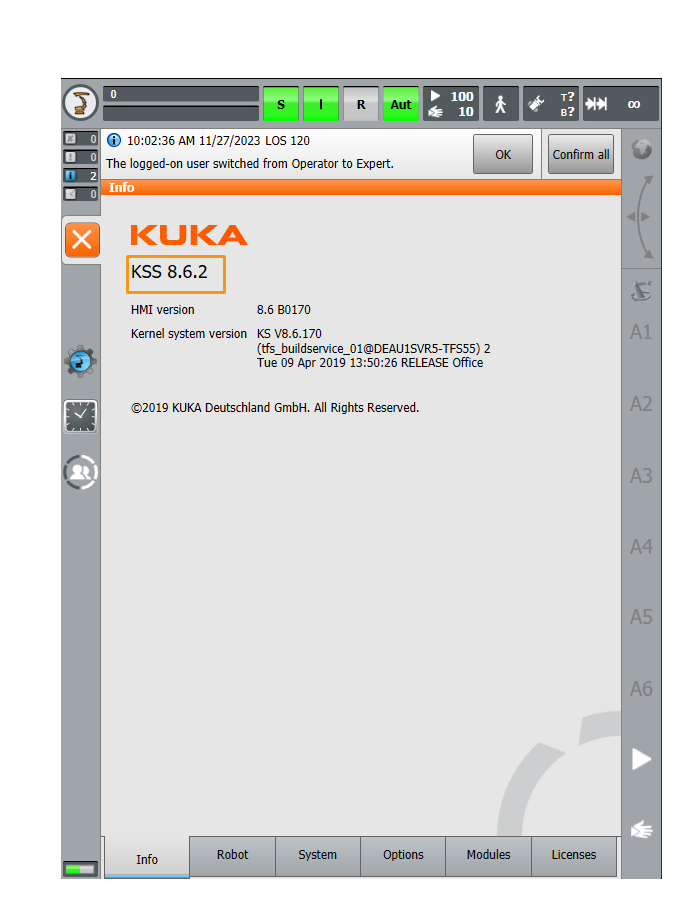
Controller system software version: KSS 8.2, 8.3, 8.5 or 8.6.
Click here for instructions
-
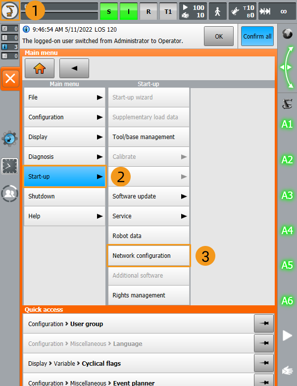
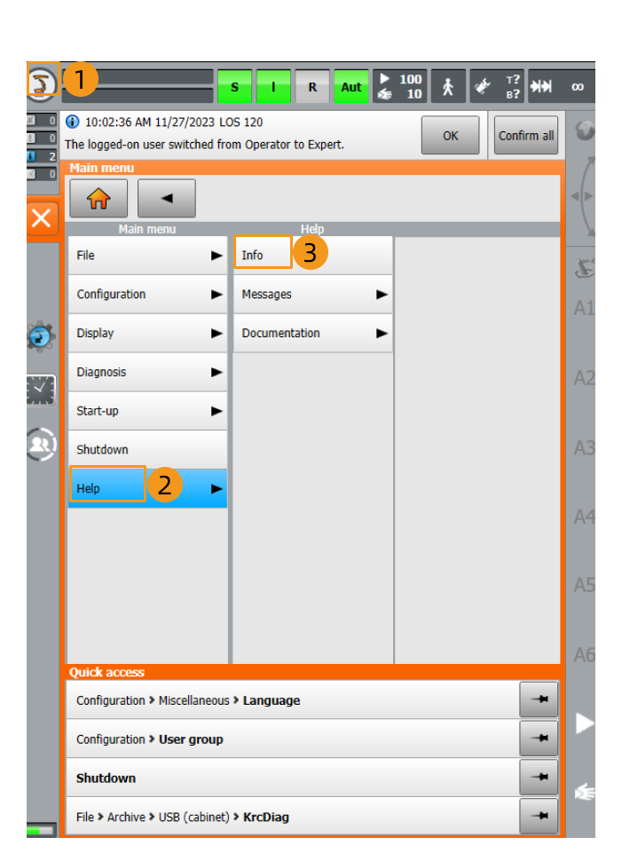
Click
 , and select .
-
Check the controller system software version in the Info interface.
-
-
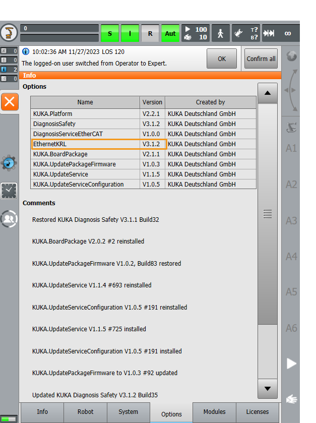
Add-on software package: Ethernet KRL (V 2.2.8, 3.0.3 or 3.1.2.29).
The correspondence between KSS and Ethernet KRL versions is as follows:
KSS version Ethernet KRL version 8.2 or 8.3
2.2.8
8.5
3.0.3
8.6
3.1.2.29
Click here for instructions
Click Options in the Info interface to view the Ethernet KRL version.
|
All teach pendant actions in this chapter are performed on KSS 8.6. The specific steps and menu selections may differ slightly in different versions of teach pendants. |
Set up the Network Connection
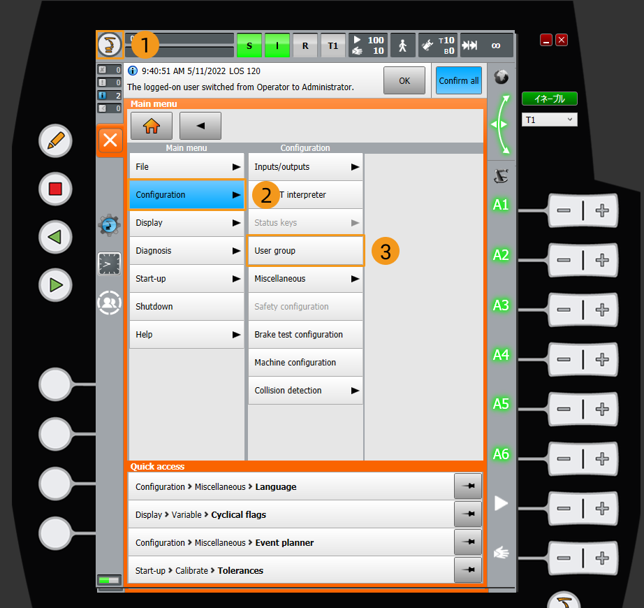
Switch to the Expert Mode
-
Click
 , and select to enter the log-on interface.
-
Select Expert, enter the password (the default password is kuka), and then click Log on.

Create a Mech-Vision Project and Save It
-
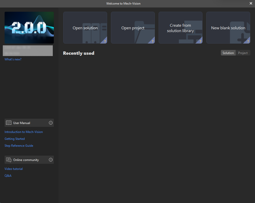
Open Mech-Vision. If the Welcome interface as shown below is displayed, it indicates that Mech-Vision is started successfully.
-
In the Welcome interface of Mech-Vision, click Create from solution library to open the Solution Library.

The Solution Library is a resource library that provides typical solutions or projects (with sample data) from various application scenarios. -
In the Application Template tab of the Solution Library, select the Random Target Object Loading solution, as shown below.
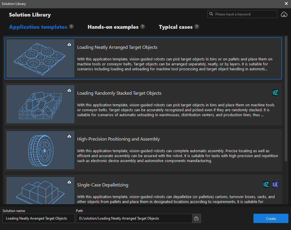
If you cannot find the Random Target Object Loading solution in the Solution Library, click the Download icon in the upper-right corner.
-
Set the solution name and path, and then click Create.
After the project is created, the created solution and project will be displayed in the project list in the upper-left corner of the Mech-Vision main interface.
-
A solution is a set of configurations and data related to robots and robot communication, vision processing, path planning, etc. that are required for the machine vision application.
-
A project is a workflow of vision processing in the solution. Normally, a solution only contains one Mech-Vision project, but it may contain more than one project in complex application scenarios.
-
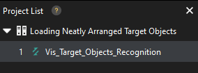
The Random Target Object Loading solution only contains one project “Vis_Target_Object_Recognition”.
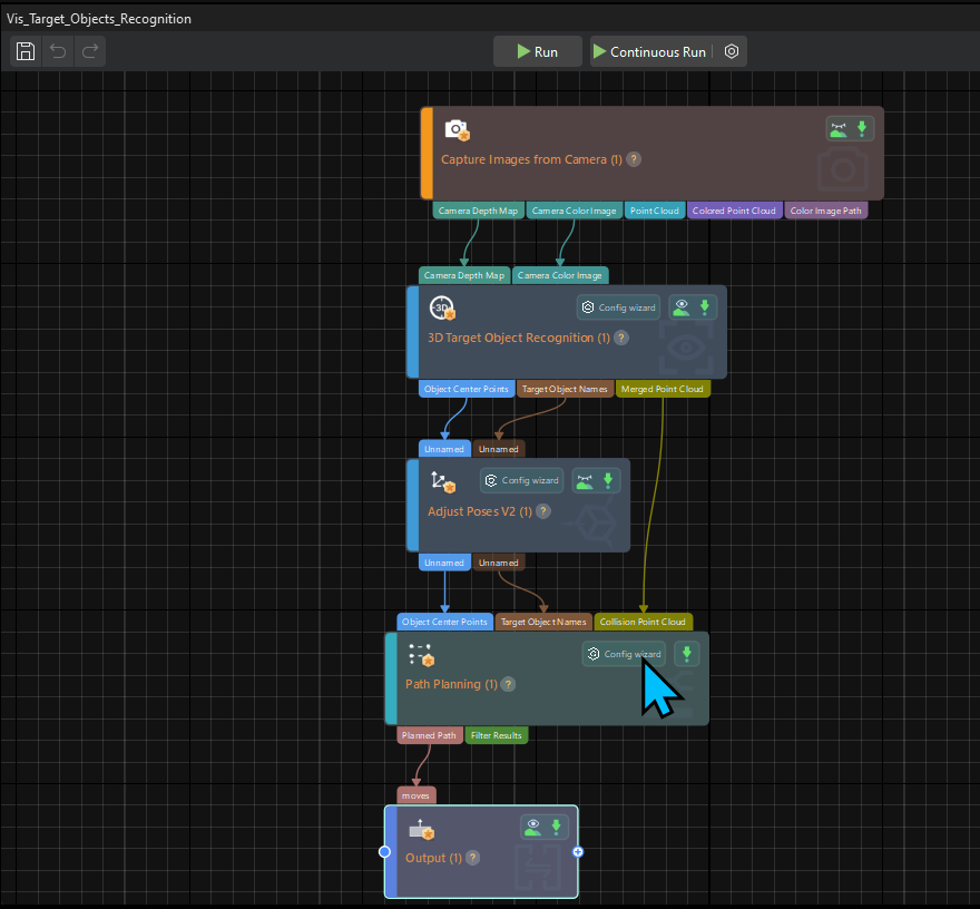
In the Graphical Programming Workspace of the main interface, the workflow of the “Vis_Target_Object_Recognition” project will be displayed.
-
-
In the project list, right-click the solution, and select Autoload Solution.
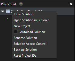
After this solution is set to autoload, the project name will be displayed in green, and the project ID will be displayed in the left of the project name.
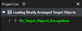
The project ID will be used by the robot pick-and-place program to trigger the Mech-Vision project to run. -
On the menu bar, select .
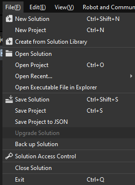
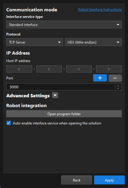
Set up Robot Communication Configuration
In this example, the robot communication configuration has been set for the KUKA robot (KUKA_KR_10_R1100_2_HO) by default. The Robot Communication Configuration option on the toolbar is enabled.
Back up the Robot Program
| Make sure you have switched to the expert mode. Otherwise, the flash drive will not show up on the teach pendant. |
-
Plug the flash drive that stores the backup file into the controller, and make sure that the flash drive shows up on the teach pendant.
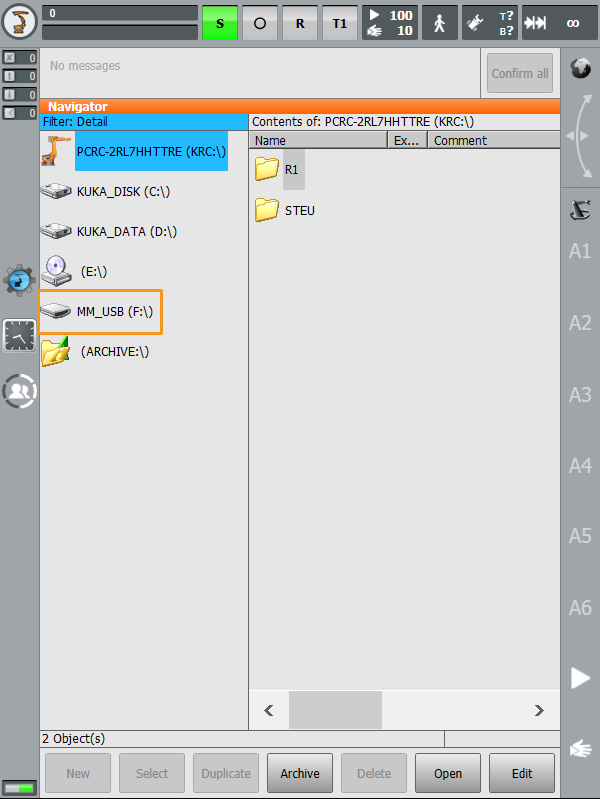
-
Click
 , select , and click Yes in the pop-up window to start the backup.
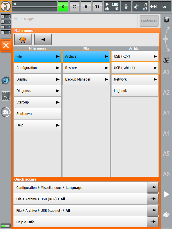
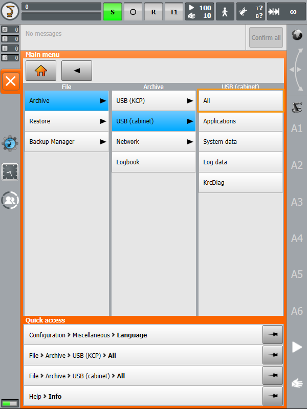
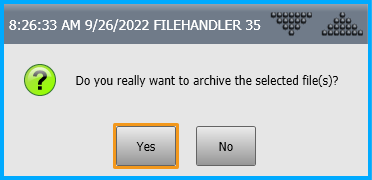
-
If the following information is displayed on the teach pendant, the backup is complete. A ZIP file is saved to the flash drive. Unplug the flash drive.

Prepare Program Files
Navigate to Communication Component\Robot_Interface from the installation directory of Mech-Vision & Mech-Viz, and copy the following KUKA folder to your flash drive.
The KUKA folder contains the following files:
-
mm_module.src (program file)
-
mm_module.dat (program file)
-
XML_Kuka_MMIND.xml (network configuration file)
-
MM_COMTEST.src (program file for testing communication)
-
MM_COMTEST.dat (program file for testing communication)
Load the Program Files to the Robot
| Make sure you have switched to the expert mode. Otherwise, the flash drive will not show up on the teach pendant. |
-
Plug the flash drive into the controller, select the flash drive on the left panel, and then locate the preceding folder.
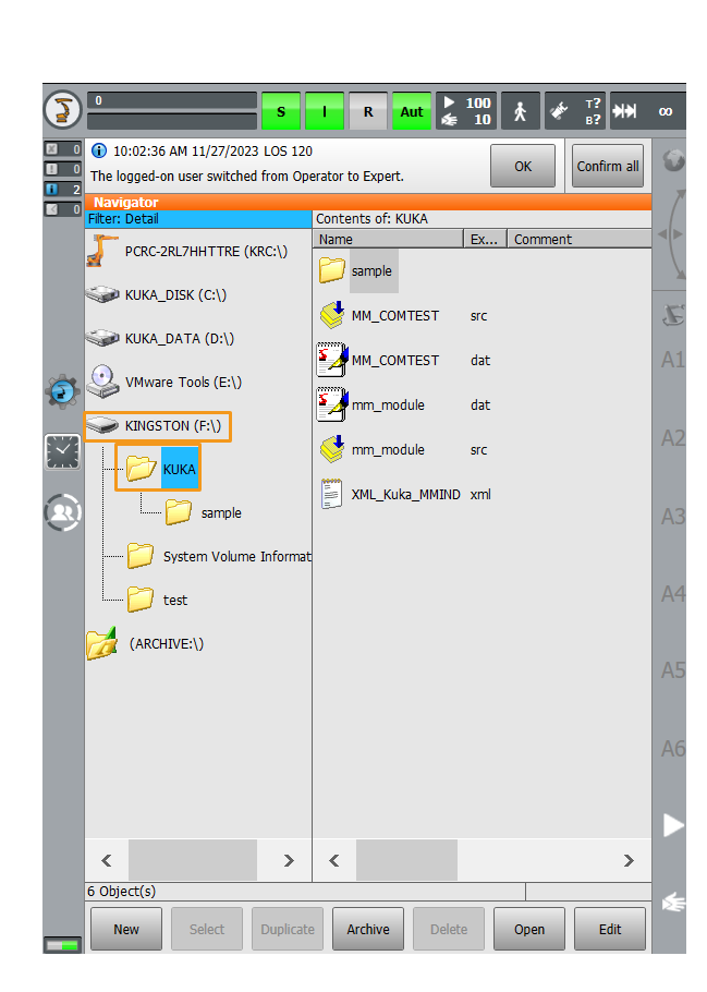
-
Copy mm_module.src, mm_module.dat, MM_COMTEST.src, and MM_COMTEST.dat to the
KRC:\R1\mmdirectory. If the mm folder does not exist, create the folder.-
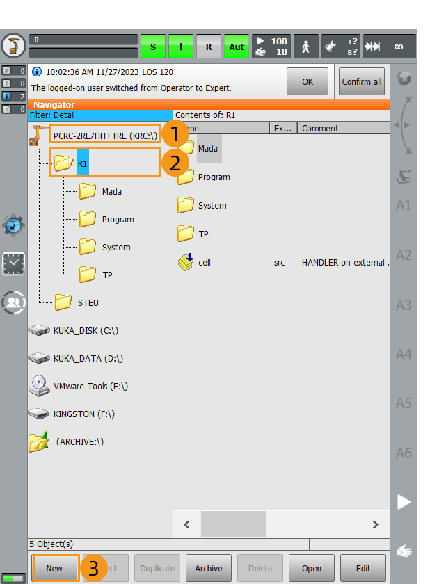
Create a mm folder.
Click KRC:\, click R1 folder, and then click New.
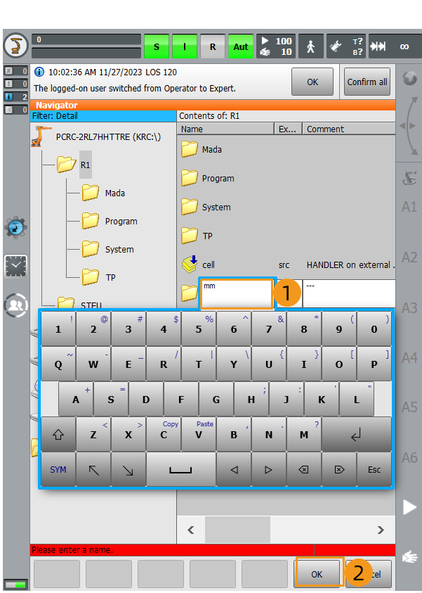
Enter mm as the folder name in the pop-up window and click OK to create the mm folder.
-
Select mm_module.src, mm_module.dat, MM_COMTEST.src, and MM_COMTEST.dat from the KUKA folder of the flash drive, click Edit, and then click Copy.
Long-press and drag to select multiple adjacent files. 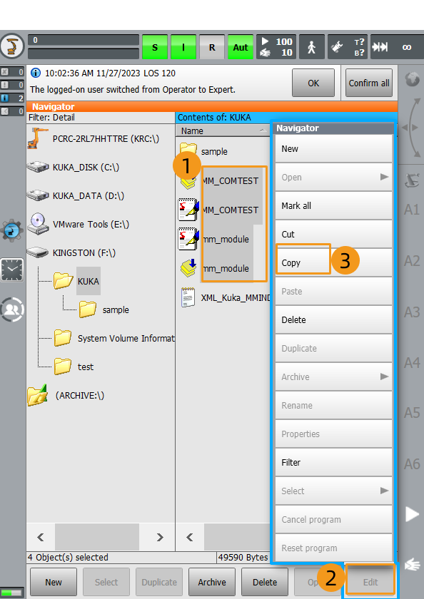
-
Select the mm folder from the
KRC:\R1directory and click Open.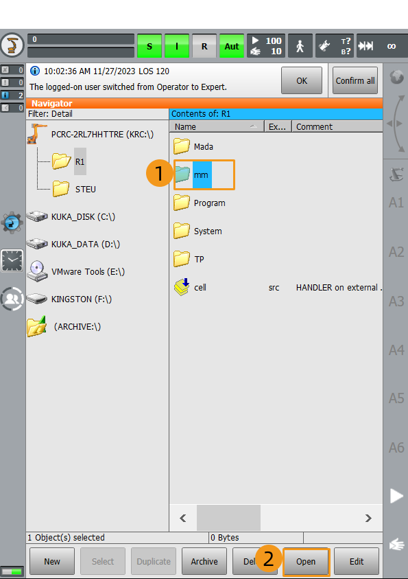
-
Select to paste the selected files.
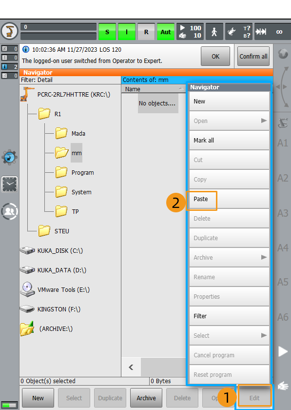
-
-
Follow the preceding steps to copy and paste XML_Kuka_MMIND.xml to
C:\KRC\ROBOTER\Config\User\Common\EthernetKRL. -
Select XML_Kuka_MMIND.xml from
C:\KRC\ROBOTER\Config\User\Common\EthernetKRLand click Open.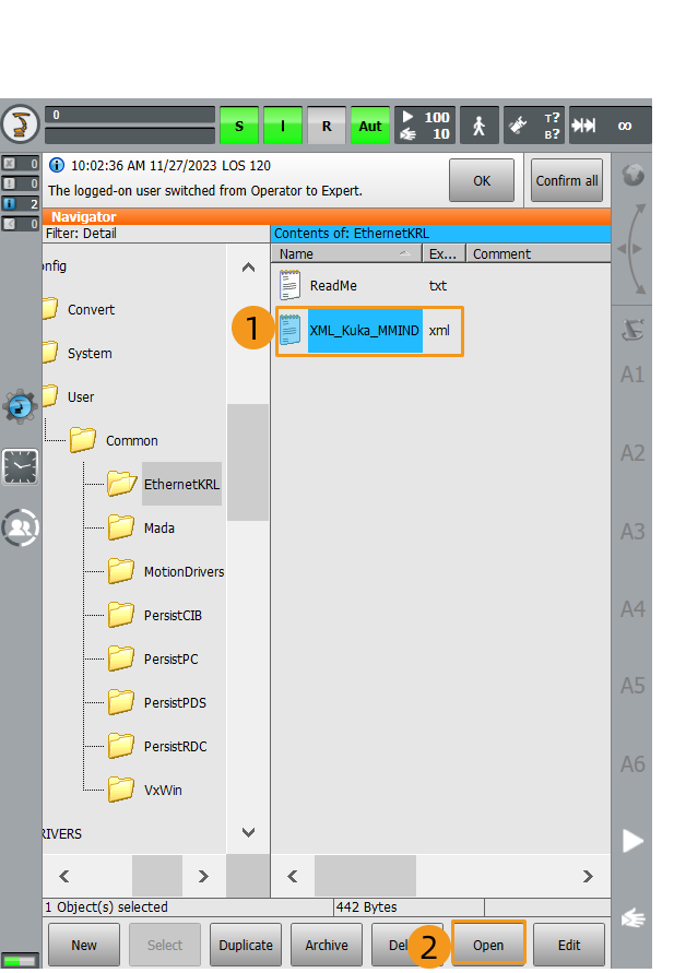
-
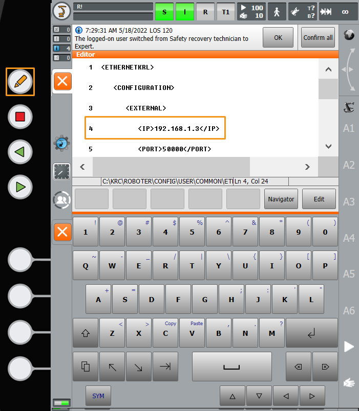
Select line 4 and click
 on the left to call out the keyboard. Change the IP address in this line to that of the IPC, and click
  again to hide the keyboard. The port number in line 5 must be the same as the port number of the host PC that is specified in Mech-Vision. To change the port number, repeat the preceding steps.
-
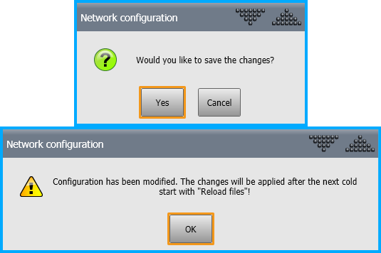
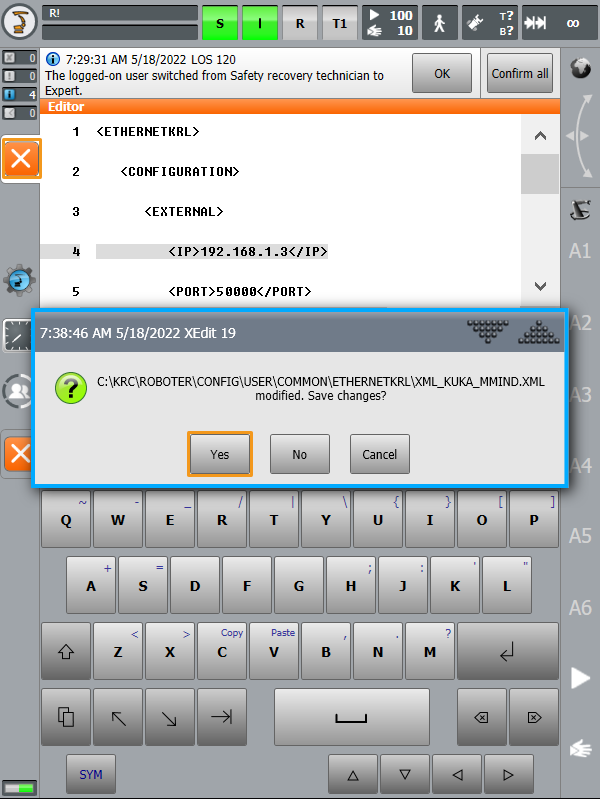
After the modification is complete, click the close button on the left. In the pop-up window, click Yes to save the modification.
-
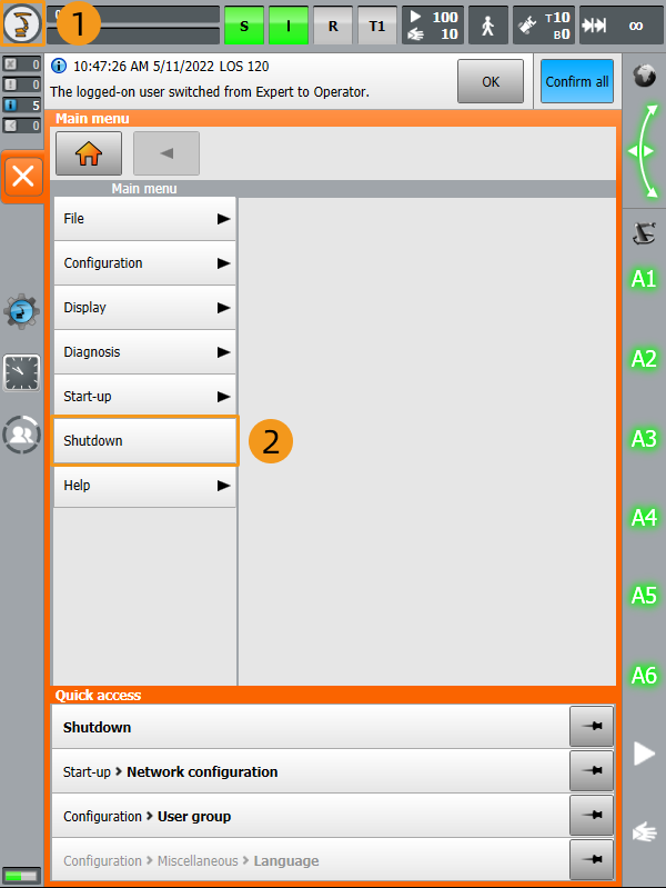
Follow the instructions in switching to the Expert mode to switch to the Administrator mode. Click
 . In the pop-up menu, select Shutdown to enter the Shutdown interface.
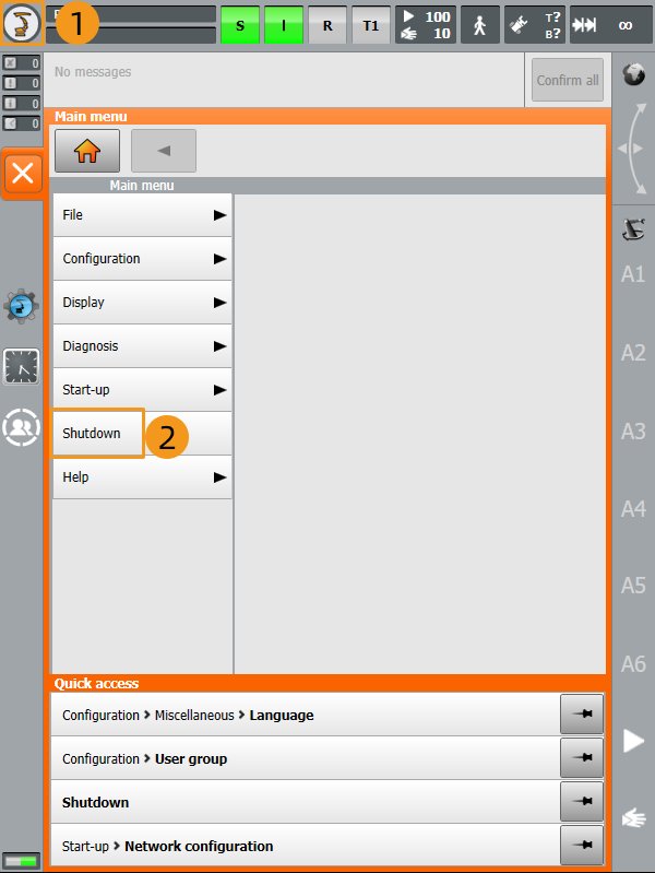
-
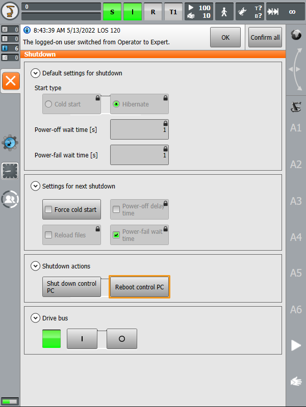
Select Cold start, Reload files, and Reboot control PC.
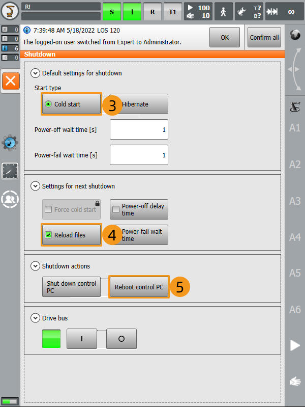
-
In the pop-up window, click Yes to restart the robot.
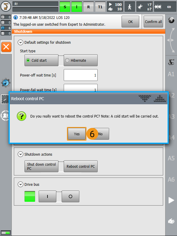
Test Standard Interface Communication
Select the Program to Test Communication
-
Follow the instructions in switching to the Expert mode to switch to the Administrator mode.
-
Open the
KRC:\R1\mmfolder, select MM_COMTEST.src, and then click Select.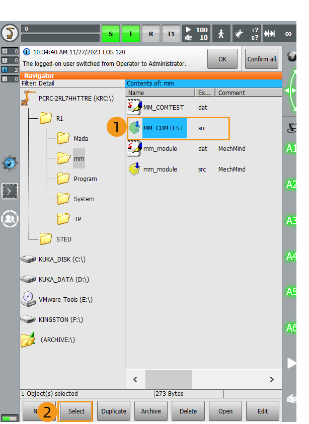
Run the Program and Test Connection
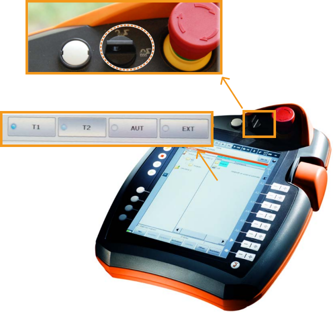
Before you start, we recommend that you see the following instructions to learn how to switch between running modes.
Turn the key switch to horizontal, select the running mode (such as T1 or AUT) in the pop-up dialog box, and then turn the switch back to vertical.
| T1 stands for the Manual Reduced Velocity mode, and AUT stands for the Automatic mode. |
-
Follow the preceding instructions to switch to the T1 mode.
-
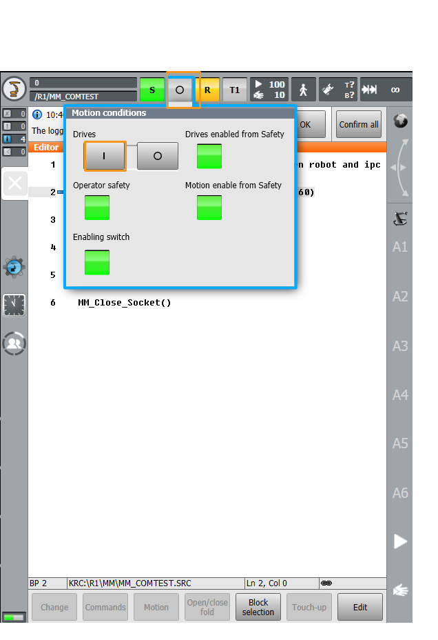
Click O. In the pop-up window, click I to set Drives to I. If Drives is already set to I, skip this step.
-
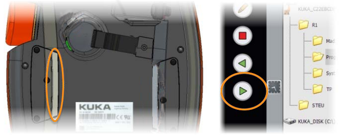
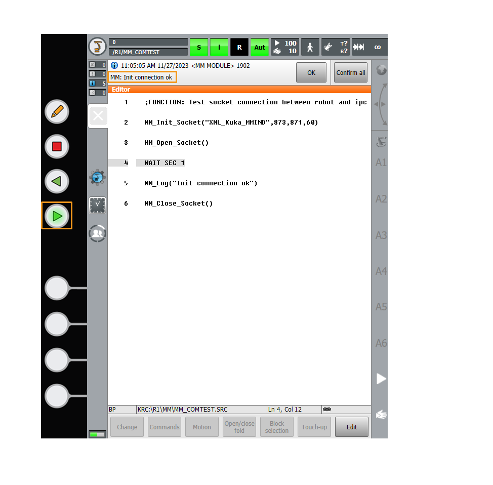
Press the white enabling switch halfway in and press the green start button to run the program. When R turns green, the program is running. After the program is run, MM:Init Connection ok is displayed. In this case, release the enabling switch and start button.
-
If the communication between the robot and the vision system is set up, a log will be recorded on the Console tab of the Log panel of Mech-Vision.

Now you have loaded the robot Standard Interface program and the configuration files to the robot system to establish the Standard Interface communication between the vision system and the robot.
